

STEVEMIT
steve/screw-terminal-block
PCB screw terminal block, Phoenix Contact types: MKDS 1,5 (5.0, 5.08 mm), PT 1,5 (3.5 mm), MPT 0,5 (2.54 mm).
PCB terminal block with push-in spring connection, Phoenix Contact types: SPT 1,5 (3.5 mm), SPT 2,5 (5.0 mm, also -EX) and SPT 5 (7.5 mm, also -ZB), horizontal or vertical.

| 1 | """PCB terminal block with push-in spring connection, Phoenix Contact SPT 1,5 (3.5 mm), SPT 2,5 (5.0 mm) and SPT 5 (7.5 mm) types, |
| 2 | horizontal (wire entries at the front) or vertical (wire entries on top). Pin 1 (its back pin) is at the origin, the row along +X, the |
| 3 | housing on the XY plane with its front facing -Y, the solder pins down through the board. Dimensions from Phoenix Contact's data sheets |
| 4 | in the README.""" |
| 5 | from steve import Model |
| 6 | |
| 7 | series = "SPT 2,5" # Series |
| 8 | style = "horizontal" # horizontal: wires enter at the front (-H-); vertical: from the top (-V-) |
| 9 | positions = 2 # Positions |
| 10 | pins = "double" # double: two solder pins per position; zigzag: one per position, alternating rows (SPT 5 ...-ZB) |
| 11 | approval = "standard" # standard, or EX: the Ex eb version of SPT 2,5 (...-EX), the same housing and pins |
| 12 | |
| 13 | # series: (pitch, pin 1 from the left end, width past dimension a (a = pitch x (positions - 1)), solder pin across the row, along it, |
| 14 | # solder pin length, positions offered) |
| 15 | # SPT 1,5: data sheet SPT 1,5/ 3-H-3,5 (1990740, 07/26/2021), Dimensions p. 2, drilling diagram p. 5 and dimensional drawing p. 6: |
| 16 | # width a + 4.9, pin 1 1.3 from the left end, pins 0.8 x 0.8, 2.5 long. |
| 17 | # SPT 2,5: data sheets SPT 2,5/ 2-H-5,0 (1990973, 01/17/2021) p. 3 and drawings p. 5, and SPT 2,5/ 2-H-5,0-EX (1732386, 03/27/2014) |
| 18 | # drawings p. 2: width a + 6.4 (11.4 for 2 positions), pin 1 2.3 from the left end, pins 0.8 x 0.8, 2.5 long. |
| 19 | # SPT 5: data sheet SPT 5/ 4-H-7,5-ZB (1719215, Feb 17, 2010) p. 1 and drawings pp. 3-4: pin 1 6.55 from the left end (drilling plan), |
| 20 | # width a + 7.5 plus a 1.8 end plate (a + 9.3), pins 1.7 x 0.8 (1.7 across the row, as the front view draws them), 4.6 long. |
| 21 | # Positions offered are the old catalogue's range for each series; the drawings give the width for any count. |
| 22 | SERIES = { |
| 23 | "SPT 1,5": (3.5, 1.3, 4.9, 0.8, 0.8, 2.5, 2, 12), |
| 24 | "SPT 2,5": (5.0, 2.3, 6.4, 0.8, 0.8, 2.5, 1, 12), |
| 25 | "SPT 5": (7.5, 6.55, 9.3, 1.7, 0.8, 4.6, 1, 12), |
| 26 | } |
| 27 | # series and style: (length front to back, height above the board, back pin row from the back face, front pin row behind the back row) |
| 28 | # SPT 1,5 horizontal: 1990740 p. 2 and p. 6: length 14.4, height 13.5 without the solder pins, rows 8.2 apart, the back row 2.53 from the back. |
| 29 | # SPT 2,5 horizontal: 1990973 p. 3 and p. 5, 1732386 p. 2: length 14.4, height 13.5, rows 8.2 apart, the back row 2.53 from the back. |
| 30 | # SPT 2,5 vertical: SPT 2,5/ 2-V-5,0-EX (1732496, Mar 27, 2024) Dimensions p. 3 and drilling plan p. 5: length 13.5, installed height 14.4, |
| 31 | # rows 8.2 apart, the back row 2.75 from the back; SPT 2,5/ 3-V-5,0 (1991105) dimensional drawing p. 6 draws the same housing. |
| 32 | # SPT 5 horizontal: 1719215 pp. 3-4: length 24.15, height 19.6, rows 13.2 apart, the back row 1.9 from the back. |
| 33 | # SPT 5 vertical: SPT 5/ 1-V-7,5 (1719309, 13/02/2015) p. 1 and p. 5, and SPT 5/ 3-V-7,5-ZB (1719325, 10.10.2012) p. 5: length 18.5, |
| 34 | # height 24.15, rows 14 apart, the back row 2.58 from the back. |
| 35 | BODY = { |
| 36 | "SPT 1,5 horizontal": (14.4, 13.5, 2.53, 8.2), |
| 37 | "SPT 2,5 horizontal": (14.4, 13.5, 2.53, 8.2), |
| 38 | "SPT 2,5 vertical": (13.5, 14.4, 2.75, 8.2), |
| 39 | "SPT 5 horizontal": (24.15, 19.6, 1.9, 13.2), |
| 40 | "SPT 5 vertical": (18.5, 24.15, 2.58, 14.0), |
| 41 | } |
| 42 | # Pin layouts: SPT 1,5 and SPT 2,5 have two pins per position (linear double pinning; drilling diagrams). SPT 5 ...-ZB: one pin per |
| 43 | # position, odd positions in the back row and even ones in the front row (drilling plans of 1719215 and 1719325); SPT 5/ 1-V-7,5 |
| 44 | # (1719309): two per position. The double-pinned SPT 5 horizontal block's drawing hasn't been read. |
| 45 | DOUBLE = {"SPT 1,5 horizontal", "SPT 2,5 horizontal", "SPT 2,5 vertical", "SPT 5 vertical"} |
| 46 | ZIGZAG = {"SPT 5 horizontal", "SPT 5 vertical"} |
| 47 | |
| 48 | key = f"{series} {style}" |
| 49 | if series not in SERIES or key not in BODY: |
| 50 | raise ValueError(f"no {style} {series} here: {', '.join(BODY)}") |
| 51 | pitch, LEFT, WIDTH_ADD, PIN_W, PIN_D, PIN_LENGTH, low, high = SERIES[series] |
| 52 | LENGTH, HEIGHT, BACK, ROWS = BODY[key] |
| 53 | if pins == "double" and key not in DOUBLE: |
| 54 | raise ValueError(f"{key}: only the zigzag (...-ZB) pin layout has been read") |
| 55 | if pins == "zigzag" and key not in ZIGZAG: |
| 56 | raise ValueError(f"{key} has two pins per position") |
| 57 | if pins == "zigzag": |
| 58 | low = 2 |
| 59 | if not low <= positions <= high: |
| 60 | raise ValueError(f"{key} comes with {low} to {high} positions") |
| 61 | if approval == "EX" and series != "SPT 2,5": |
| 62 | raise ValueError("the EX version is SPT 2,5") |
| 63 | |
| 64 | width = (positions - 1) * pitch + WIDTH_ADD |
| 65 | x0 = -LEFT |
| 66 | front = BACK - LENGTH |
| 67 | # Proportions, for looks only (the drawings don't dimension them): the chamfers on the housing's top edges, the wire entry, the release |
| 68 | # slot above (horizontal) or in front of (vertical) it, and how deep they go. |
| 69 | CHAMFER = 0.06 * HEIGHT |
| 70 | ENTRY = 0.62 * pitch |
| 71 | SLOT_W = 0.5 * pitch |
| 72 | SLOT_H = 0.16 * HEIGHT |
| 73 | ENTRY_DEPTH = 0.55 * LENGTH |
| 74 | SLOT_DEPTH = 0.3 * LENGTH |
| 75 | |
| 76 | model = Model() |
| 77 | # The housing: its side outline in the YZ plane, extruded along +X. |
| 78 | profile = [(front, 0), (BACK, 0), (BACK, HEIGHT - CHAMFER), (BACK - CHAMFER, HEIGHT), (front + CHAMFER, HEIGHT), (front, HEIGHT - CHAMFER)] |
| 79 | model.plane("side_plane", on="YZ", offset=x0, name="Side") |
| 80 | with model.sketch("body_sketch", on="side_plane", name="Housing") as sk: |
| 81 | sk.polyline("body_outline", profile, closed=True) |
| 82 | model.extrude("body", "body_sketch", distance=width, op="new", body="housing_body", name="Housing") |
| 83 | if style == "horizontal": |
| 84 | # The XZ plane's normal is -Y: offset -front puts the plane on the front face, and a negative distance cuts towards +Y. |
| 85 | entry_z = 0.38 * HEIGHT |
| 86 | slot_z = 0.72 * HEIGHT |
| 87 | model.plane("front_plane", on="XZ", offset=-front, name="Front") |
| 88 | with model.sketch("entries_sketch", on="front_plane", name="Wire entries") as sk: |
| 89 | for i in range(positions): |
| 90 | if series == "SPT 5": |
| 91 | sk.rect(f"entry_{i}", (i * pitch - ENTRY / 2, entry_z - ENTRY / 2), (i * pitch + ENTRY / 2, entry_z + ENTRY / 2)) |
| 92 | else: |
| 93 | sk.circle(f"entry_{i}", (i * pitch, entry_z), ENTRY / 2) |
| 94 | model.extrude("entries", "entries_sketch", distance=-ENTRY_DEPTH, op="cut", body="housing_body", name="Wire entries") |
| 95 | with model.sketch("slots_sketch", on="front_plane", name="Release slots") as sk: |
| 96 | for i in range(positions): |
| 97 | sk.rect(f"slot_{i}", (i * pitch - SLOT_W / 2, slot_z - SLOT_H / 2), (i * pitch + SLOT_W / 2, slot_z + SLOT_H / 2)) |
| 98 | model.extrude("slots", "slots_sketch", distance=-SLOT_DEPTH, op="cut", body="housing_body", name="Release slots") |
| 99 | else: |
| 100 | entry_y = BACK - 0.33 * LENGTH |
| 101 | slot_y = front + 0.25 * LENGTH |
| 102 | model.plane("top_plane", on="XY", offset=HEIGHT, name="Top") |
| 103 | with model.sketch("entries_sketch", on="top_plane", name="Wire entries") as sk: |
| 104 | for i in range(positions): |
| 105 | if series == "SPT 5": |
| 106 | sk.rect(f"entry_{i}", (i * pitch - ENTRY / 2, entry_y - ENTRY / 2), (i * pitch + ENTRY / 2, entry_y + ENTRY / 2)) |
| 107 | else: |
| 108 | sk.circle(f"entry_{i}", (i * pitch, entry_y), ENTRY / 2) |
| 109 | model.extrude("entries", "entries_sketch", distance=-0.55 * HEIGHT, op="cut", body="housing_body", name="Wire entries") |
| 110 | with model.sketch("slots_sketch", on="top_plane", name="Release slots") as sk: |
| 111 | for i in range(positions): |
| 112 | sk.rect(f"slot_{i}", (i * pitch - SLOT_W / 2, slot_y - 0.16 * LENGTH / 2), (i * pitch + SLOT_W / 2, slot_y + 0.16 * LENGTH / 2)) |
| 113 | model.extrude("slots", "slots_sketch", distance=-0.3 * HEIGHT, op="cut", body="housing_body", name="Release slots") |
| 114 | # Contacts: each position's solder pins and the bar joining them inside the housing's floor are one solid. The bar is a proportion |
| 115 | # (BAR_W x BAR_T, from the back pin to the front pin's row), standing for the current bar and spring the sections draw, so that the |
| 116 | # mass comes out near the data sheets' weights. |
| 117 | BAR_W = 0.5 * pitch |
| 118 | BAR_T = 1.0 |
| 119 | bar_y = (-ROWS - PIN_D / 2, PIN_D / 2) |
| 120 | with model.sketch("bars_sketch", on="XY", name="Contact bars") as sk: |
| 121 | for i in range(positions): |
| 122 | sk.rect(f"bar_cut_{i}", (i * pitch - BAR_W / 2, bar_y[0]), (i * pitch + BAR_W / 2, bar_y[1])) |
| 123 | model.extrude("bar_room", "bars_sketch", distance=BAR_T, op="cut", body="housing_body", name="Room for the contacts") |
| 124 | model.plane("pin_plane", on="XY", offset=-PIN_LENGTH, name="Solder pins") |
| 125 | contacts = [] |
| 126 | for i in range(positions): |
| 127 | rows = [0.0, -ROWS] if pins == "double" else [0.0 if i % 2 == 0 else -ROWS] |
| 128 | with model.sketch(f"pins_{i}_sketch", on="pin_plane", name=f"Solder pins {i + 1}") as sk: |
| 129 | for j, y in enumerate(rows): |
| 130 | sk.rect(f"pin_{i}_{j}", (i * pitch - PIN_W / 2, y - PIN_D / 2), (i * pitch + PIN_W / 2, y + PIN_D / 2)) |
| 131 | model.extrude(f"pins_{i}", f"pins_{i}_sketch", distance=PIN_LENGTH + BAR_T / 2, op="new", body=f"contact_{i}_body", name=f"Solder pins {i + 1}") |
| 132 | model.box(f"bar_{i}", BAR_W, bar_y[1] - bar_y[0], BAR_T, at=(i * pitch, (bar_y[0] + bar_y[1]) / 2, BAR_T / 2), op="join", |
| 133 | body=f"contact_{i}_body", name=f"Contact bar {i + 1}") |
| 134 | contacts.append(f"contact_{i}_body") |
| 135 | # Materials: the housing is PA, green RAL 6021 (data sheets); the contacts copper alloy, tin plated. |
| 136 | model.material("pa6", bodies=["housing_body"], color="#89ac76") |
| 137 | model.material("copper", bodies=contacts, color="#c9cbc8") |
| 138 | result = model.result() |
| 139 |
| 1 | name = "steve/push-in-terminal-block" |
| 2 | version = "1.0.0" |
| 3 | runtime = "steve" |
| 4 | license = "MIT" |
| 5 | summary = "PCB terminal block with push-in spring connection, Phoenix Contact types: SPT 1,5 (3.5 mm), SPT 2,5 (5.0 mm, also -EX) and SPT 5 (7.5 mm, also -ZB), horizontal or vertical." |
| 6 | description = """PCB terminal block with push-in spring connection, of the Phoenix Contact SPT 1,5 (3.5 mm, horizontal), SPT 2,5 (5.0 mm, horizontal or vertical, standard or Ex eb) or SPT 5 (7.5 mm, horizontal or vertical, two pins per position or zigzag -ZB) type, with wire entries, release slots and solder pins. Width, length, height and pins from Phoenix Contact's data sheets. See the README.""" |
| 7 | tags = ["terminal-block", "push-in", "spring-terminal", "phoenix", "spt", "connector", "electronics"] |
| 8 | |
| 9 | [parameters.series] |
| 10 | type = "choice" |
| 11 | default = "SPT 2,5" |
| 12 | choices = ["SPT 1,5", "SPT 2,5", "SPT 5"] |
| 13 | label = "Series" |
| 14 | description = "SPT 1,5: 3.5 mm pitch. SPT 2,5: 5.0 mm. SPT 5: 7.5 mm." |
| 15 | |
| 16 | [parameters.style] |
| 17 | type = "choice" |
| 18 | default = "horizontal" |
| 19 | choices = ["horizontal", "vertical"] |
| 20 | label = "Style" |
| 21 | description = "horizontal (-H-): wires enter at the front. vertical (-V-): from the top. SPT 1,5 is horizontal only." |
| 22 | |
| 23 | [parameters.positions] |
| 24 | type = "integer" |
| 25 | default = 2 |
| 26 | min = 1 |
| 27 | max = 12 |
| 28 | label = "Positions" |
| 29 | description = "SPT 1,5 and vertical SPT 2,5: 2 to 12. Horizontal SPT 2,5 and SPT 5: 1 to 12. Zigzag pins: 2 to 12." |
| 30 | |
| 31 | [parameters.pins] |
| 32 | type = "choice" |
| 33 | default = "double" |
| 34 | choices = ["double", "zigzag"] |
| 35 | label = "Pin layout" |
| 36 | description = "double: two solder pins per position. zigzag: one per position, alternating rows (SPT 5 ...-ZB). Horizontal SPT 5 is zigzag only." |
| 37 | |
| 38 | [parameters.approval] |
| 39 | type = "choice" |
| 40 | default = "standard" |
| 41 | choices = ["standard", "EX"] |
| 42 | label = "Version" |
| 43 | description = "EX: the Ex eb version of SPT 2,5 (...-EX), with the same housing and pins." |
| 44 |
| 1 | # Presets of this part (factory/PRESETS.md). Written by factory/gen.py. |
| 2 | |
| 3 | [[presets]] |
| 4 | id = "SPT1.5-2-H-3.5" |
| 5 | title = "Push-in PCB terminal block, 2 positions, 3.5 mm, horizontal (SPT 1,5/2-H-3,5)" |
| 6 | params = { series = "SPT 1,5", style = "horizontal", positions = 2 } |
| 7 | aliases = ["SPT 1,5/2-H-3,5", "SPT 1,5/ 2-H-3,5", "SPT 1.5/2-H-3.5", "2 way push-in terminal block 3.5mm horizontal"] |
| 8 | standard = "Phoenix Contact" |
| 9 | |
| 10 | [[presets]] |
| 11 | id = "SPT1.5-3-H-3.5" |
| 12 | title = "Push-in PCB terminal block, 3 positions, 3.5 mm, horizontal (SPT 1,5/3-H-3,5)" |
| 13 | params = { series = "SPT 1,5", style = "horizontal", positions = 3 } |
| 14 | aliases = ["SPT 1,5/3-H-3,5", "SPT 1,5/ 3-H-3,5", "SPT 1.5/3-H-3.5", "3 way push-in terminal block 3.5mm horizontal"] |
| 15 | standard = "Phoenix Contact" |
| 16 | |
| 17 | [[presets]] |
| 18 | id = "SPT1.5-4-H-3.5" |
| 19 | title = "Push-in PCB terminal block, 4 positions, 3.5 mm, horizontal (SPT 1,5/4-H-3,5)" |
| 20 | params = { series = "SPT 1,5", style = "horizontal", positions = 4 } |
| 21 | aliases = ["SPT 1,5/4-H-3,5", "SPT 1,5/ 4-H-3,5", "SPT 1.5/4-H-3.5", "4 way push-in terminal block 3.5mm horizontal"] |
| 22 | standard = "Phoenix Contact" |
| 23 | |
| 24 | [[presets]] |
| 25 | id = "SPT1.5-5-H-3.5" |
| 26 | title = "Push-in PCB terminal block, 5 positions, 3.5 mm, horizontal (SPT 1,5/5-H-3,5)" |
| 27 | params = { series = "SPT 1,5", style = "horizontal", positions = 5 } |
| 28 | aliases = ["SPT 1,5/5-H-3,5", "SPT 1,5/ 5-H-3,5", "SPT 1.5/5-H-3.5", "5 way push-in terminal block 3.5mm horizontal"] |
| 29 | standard = "Phoenix Contact" |
| 30 | |
| 31 | [[presets]] |
| 32 | id = "SPT1.5-6-H-3.5" |
| 33 | title = "Push-in PCB terminal block, 6 positions, 3.5 mm, horizontal (SPT 1,5/6-H-3,5)" |
| 34 | params = { series = "SPT 1,5", style = "horizontal", positions = 6 } |
| 35 | aliases = ["SPT 1,5/6-H-3,5", "SPT 1,5/ 6-H-3,5", "SPT 1.5/6-H-3.5", "6 way push-in terminal block 3.5mm horizontal"] |
| 36 | standard = "Phoenix Contact" |
| 37 | |
| 38 | [[presets]] |
| 39 | id = "SPT1.5-7-H-3.5" |
| 40 | title = "Push-in PCB terminal block, 7 positions, 3.5 mm, horizontal (SPT 1,5/7-H-3,5)" |
| 41 | params = { series = "SPT 1,5", style = "horizontal", positions = 7 } |
| 42 | aliases = ["SPT 1,5/7-H-3,5", "SPT 1,5/ 7-H-3,5", "SPT 1.5/7-H-3.5", "7 way push-in terminal block 3.5mm horizontal"] |
| 43 | standard = "Phoenix Contact" |
| 44 | |
| 45 | [[presets]] |
| 46 | id = "SPT1.5-8-H-3.5" |
| 47 | title = "Push-in PCB terminal block, 8 positions, 3.5 mm, horizontal (SPT 1,5/8-H-3,5)" |
| 48 | params = { series = "SPT 1,5", style = "horizontal", positions = 8 } |
| 49 | aliases = ["SPT 1,5/8-H-3,5", "SPT 1,5/ 8-H-3,5", "SPT 1.5/8-H-3.5", "8 way push-in terminal block 3.5mm horizontal"] |
| 50 | standard = "Phoenix Contact" |
| 51 | |
| 52 | [[presets]] |
| 53 | id = "SPT1.5-9-H-3.5" |
| 54 | title = "Push-in PCB terminal block, 9 positions, 3.5 mm, horizontal (SPT 1,5/9-H-3,5)" |
| 55 | params = { series = "SPT 1,5", style = "horizontal", positions = 9 } |
| 56 | aliases = ["SPT 1,5/9-H-3,5", "SPT 1,5/ 9-H-3,5", "SPT 1.5/9-H-3.5", "9 way push-in terminal block 3.5mm horizontal"] |
| 57 | standard = "Phoenix Contact" |
| 58 | |
| 59 | [[presets]] |
| 60 | id = "SPT1.5-10-H-3.5" |
| 61 | title = "Push-in PCB terminal block, 10 positions, 3.5 mm, horizontal (SPT 1,5/10-H-3,5)" |
| 62 | params = { series = "SPT 1,5", style = "horizontal", positions = 10 } |
| 63 | aliases = ["SPT 1,5/10-H-3,5", "SPT 1.5/10-H-3.5", "10 way push-in terminal block 3.5mm horizontal"] |
| 64 | standard = "Phoenix Contact" |
| 65 | |
| 66 | [[presets]] |
| 67 | id = "SPT1.5-11-H-3.5" |
| 68 | title = "Push-in PCB terminal block, 11 positions, 3.5 mm, horizontal (SPT 1,5/11-H-3,5)" |
| 69 | params = { series = "SPT 1,5", style = "horizontal", positions = 11 } |
| 70 | aliases = ["SPT 1,5/11-H-3,5", "SPT 1.5/11-H-3.5", "11 way push-in terminal block 3.5mm horizontal"] |
| 71 | standard = "Phoenix Contact" |
| 72 | |
| 73 | [[presets]] |
| 74 | id = "SPT1.5-12-H-3.5" |
| 75 | title = "Push-in PCB terminal block, 12 positions, 3.5 mm, horizontal (SPT 1,5/12-H-3,5)" |
| 76 | params = { series = "SPT 1,5", style = "horizontal", positions = 12 } |
| 77 | aliases = ["SPT 1,5/12-H-3,5", "SPT 1.5/12-H-3.5", "12 way push-in terminal block 3.5mm horizontal"] |
| 78 | standard = "Phoenix Contact" |
| 79 | |
| 80 | [[presets]] |
| 81 | id = "SPT2.5-2-H-5.0-EX" |
| 82 | title = "Push-in PCB terminal block, 2 positions, 5.0 mm, horizontal, Ex eb version (SPT 2,5/2-H-5,0-EX)" |
| 83 | params = { series = "SPT 2,5", style = "horizontal", positions = 2, approval = "EX" } |
| 84 | aliases = ["SPT 2,5/2-H-5,0-EX", "SPT 2,5/ 2-H-5,0-EX", "SPT 2.5/2-H-5.0-EX", "2 way push-in terminal block 5.0mm horizontal"] |
| 85 | standard = "Phoenix Contact" |
| 86 | |
| 87 | [[presets]] |
| 88 | id = "SPT2.5-3-H-5.0-EX" |
| 89 | title = "Push-in PCB terminal block, 3 positions, 5.0 mm, horizontal, Ex eb version (SPT 2,5/3-H-5,0-EX)" |
| 90 | params = { series = "SPT 2,5", style = "horizontal", positions = 3, approval = "EX" } |
| 91 | aliases = ["SPT 2,5/3-H-5,0-EX", "SPT 2,5/ 3-H-5,0-EX", "SPT 2.5/3-H-5.0-EX", "3 way push-in terminal block 5.0mm horizontal"] |
| 92 | standard = "Phoenix Contact" |
| 93 | |
| 94 | [[presets]] |
| 95 | id = "SPT2.5-4-H-5.0-EX" |
| 96 | title = "Push-in PCB terminal block, 4 positions, 5.0 mm, horizontal, Ex eb version (SPT 2,5/4-H-5,0-EX)" |
| 97 | params = { series = "SPT 2,5", style = "horizontal", positions = 4, approval = "EX" } |
| 98 | aliases = ["SPT 2,5/4-H-5,0-EX", "SPT 2,5/ 4-H-5,0-EX", "SPT 2.5/4-H-5.0-EX", "4 way push-in terminal block 5.0mm horizontal"] |
| 99 | standard = "Phoenix Contact" |
| 100 | |
| 101 | [[presets]] |
| 102 | id = "SPT2.5-5-H-5.0-EX" |
| 103 | title = "Push-in PCB terminal block, 5 positions, 5.0 mm, horizontal, Ex eb version (SPT 2,5/5-H-5,0-EX)" |
| 104 | params = { series = "SPT 2,5", style = "horizontal", positions = 5, approval = "EX" } |
| 105 | aliases = ["SPT 2,5/5-H-5,0-EX", "SPT 2,5/ 5-H-5,0-EX", "SPT 2.5/5-H-5.0-EX", "5 way push-in terminal block 5.0mm horizontal"] |
| 106 | standard = "Phoenix Contact" |
| 107 | |
| 108 | [[presets]] |
| 109 | id = "SPT2.5-6-H-5.0-EX" |
| 110 | title = "Push-in PCB terminal block, 6 positions, 5.0 mm, horizontal, Ex eb version (SPT 2,5/6-H-5,0-EX)" |
| 111 | params = { series = "SPT 2,5", style = "horizontal", positions = 6, approval = "EX" } |
| 112 | aliases = ["SPT 2,5/6-H-5,0-EX", "SPT 2,5/ 6-H-5,0-EX", "SPT 2.5/6-H-5.0-EX", "6 way push-in terminal block 5.0mm horizontal"] |
| 113 | standard = "Phoenix Contact" |
| 114 | |
| 115 | [[presets]] |
| 116 | id = "SPT2.5-7-H-5.0-EX" |
| 117 | title = "Push-in PCB terminal block, 7 positions, 5.0 mm, horizontal, Ex eb version (SPT 2,5/7-H-5,0-EX)" |
| 118 | params = { series = "SPT 2,5", style = "horizontal", positions = 7, approval = "EX" } |
| 119 | aliases = ["SPT 2,5/7-H-5,0-EX", "SPT 2,5/ 7-H-5,0-EX", "SPT 2.5/7-H-5.0-EX", "7 way push-in terminal block 5.0mm horizontal"] |
| 120 | standard = "Phoenix Contact" |
| 121 | |
| 122 | [[presets]] |
| 123 | id = "SPT2.5-8-H-5.0-EX" |
| 124 | title = "Push-in PCB terminal block, 8 positions, 5.0 mm, horizontal, Ex eb version (SPT 2,5/8-H-5,0-EX)" |
| 125 | params = { series = "SPT 2,5", style = "horizontal", positions = 8, approval = "EX" } |
| 126 | aliases = ["SPT 2,5/8-H-5,0-EX", "SPT 2,5/ 8-H-5,0-EX", "SPT 2.5/8-H-5.0-EX", "8 way push-in terminal block 5.0mm horizontal"] |
| 127 | standard = "Phoenix Contact" |
| 128 | |
| 129 | [[presets]] |
| 130 | id = "SPT2.5-9-H-5.0-EX" |
| 131 | title = "Push-in PCB terminal block, 9 positions, 5.0 mm, horizontal, Ex eb version (SPT 2,5/9-H-5,0-EX)" |
| 132 | params = { series = "SPT 2,5", style = "horizontal", positions = 9, approval = "EX" } |
| 133 | aliases = ["SPT 2,5/9-H-5,0-EX", "SPT 2,5/ 9-H-5,0-EX", "SPT 2.5/9-H-5.0-EX", "9 way push-in terminal block 5.0mm horizontal"] |
| 134 | standard = "Phoenix Contact" |
| 135 | |
| 136 | [[presets]] |
| 137 | id = "SPT2.5-10-H-5.0-EX" |
| 138 | title = "Push-in PCB terminal block, 10 positions, 5.0 mm, horizontal, Ex eb version (SPT 2,5/10-H-5,0-EX)" |
| 139 | params = { series = "SPT 2,5", style = "horizontal", positions = 10, approval = "EX" } |
| 140 | aliases = ["SPT 2,5/10-H-5,0-EX", "SPT 2.5/10-H-5.0-EX", "10 way push-in terminal block 5.0mm horizontal"] |
| 141 | standard = "Phoenix Contact" |
| 142 | |
| 143 | [[presets]] |
| 144 | id = "SPT2.5-11-H-5.0-EX" |
| 145 | title = "Push-in PCB terminal block, 11 positions, 5.0 mm, horizontal, Ex eb version (SPT 2,5/11-H-5,0-EX)" |
| 146 | params = { series = "SPT 2,5", style = "horizontal", positions = 11, approval = "EX" } |
| 147 | aliases = ["SPT 2,5/11-H-5,0-EX", "SPT 2.5/11-H-5.0-EX", "11 way push-in terminal block 5.0mm horizontal"] |
| 148 | standard = "Phoenix Contact" |
| 149 | |
| 150 | [[presets]] |
| 151 | id = "SPT2.5-12-H-5.0-EX" |
| 152 | title = "Push-in PCB terminal block, 12 positions, 5.0 mm, horizontal, Ex eb version (SPT 2,5/12-H-5,0-EX)" |
| 153 | params = { series = "SPT 2,5", style = "horizontal", positions = 12, approval = "EX" } |
| 154 | aliases = ["SPT 2,5/12-H-5,0-EX", "SPT 2.5/12-H-5.0-EX", "12 way push-in terminal block 5.0mm horizontal"] |
| 155 | standard = "Phoenix Contact" |
| 156 | |
| 157 | [[presets]] |
| 158 | id = "SPT2.5-1-H-5.0" |
| 159 | title = "Push-in PCB terminal block, 1 position, 5.0 mm, horizontal (SPT 2,5/1-H-5,0)" |
| 160 | params = { series = "SPT 2,5", style = "horizontal", positions = 1 } |
| 161 | aliases = ["SPT 2,5/1-H-5,0", "SPT 2,5/ 1-H-5,0", "SPT 2.5/1-H-5.0", "1 way push-in terminal block 5.0mm horizontal"] |
| 162 | standard = "Phoenix Contact" |
| 163 | |
| 164 | [[presets]] |
| 165 | id = "SPT2.5-2-H-5.0" |
| 166 | title = "Push-in PCB terminal block, 2 positions, 5.0 mm, horizontal (SPT 2,5/2-H-5,0)" |
| 167 | params = { series = "SPT 2,5", style = "horizontal", positions = 2 } |
| 168 | aliases = ["SPT 2,5/2-H-5,0", "SPT 2,5/ 2-H-5,0", "SPT 2.5/2-H-5.0", "2 way push-in terminal block 5.0mm horizontal"] |
| 169 | standard = "Phoenix Contact" |
| 170 | |
| 171 | [[presets]] |
| 172 | id = "SPT2.5-3-H-5.0" |
| 173 | title = "Push-in PCB terminal block, 3 positions, 5.0 mm, horizontal (SPT 2,5/3-H-5,0)" |
| 174 | params = { series = "SPT 2,5", style = "horizontal", positions = 3 } |
| 175 | aliases = ["SPT 2,5/3-H-5,0", "SPT 2,5/ 3-H-5,0", "SPT 2.5/3-H-5.0", "3 way push-in terminal block 5.0mm horizontal"] |
| 176 | standard = "Phoenix Contact" |
| 177 | |
| 178 | [[presets]] |
| 179 | id = "SPT2.5-4-H-5.0" |
| 180 | title = "Push-in PCB terminal block, 4 positions, 5.0 mm, horizontal (SPT 2,5/4-H-5,0)" |
| 181 | params = { series = "SPT 2,5", style = "horizontal", positions = 4 } |
| 182 | aliases = ["SPT 2,5/4-H-5,0", "SPT 2,5/ 4-H-5,0", "SPT 2.5/4-H-5.0", "4 way push-in terminal block 5.0mm horizontal"] |
| 183 | standard = "Phoenix Contact" |
| 184 | |
| 185 | [[presets]] |
| 186 | id = "SPT2.5-5-H-5.0" |
| 187 | title = "Push-in PCB terminal block, 5 positions, 5.0 mm, horizontal (SPT 2,5/5-H-5,0)" |
| 188 | params = { series = "SPT 2,5", style = "horizontal", positions = 5 } |
| 189 | aliases = ["SPT 2,5/5-H-5,0", "SPT 2,5/ 5-H-5,0", "SPT 2.5/5-H-5.0", "5 way push-in terminal block 5.0mm horizontal"] |
| 190 | standard = "Phoenix Contact" |
| 191 | |
| 192 | [[presets]] |
| 193 | id = "SPT2.5-6-H-5.0" |
| 194 | title = "Push-in PCB terminal block, 6 positions, 5.0 mm, horizontal (SPT 2,5/6-H-5,0)" |
| 195 | params = { series = "SPT 2,5", style = "horizontal", positions = 6 } |
| 196 | aliases = ["SPT 2,5/6-H-5,0", "SPT 2,5/ 6-H-5,0", "SPT 2.5/6-H-5.0", "6 way push-in terminal block 5.0mm horizontal"] |
| 197 | standard = "Phoenix Contact" |
| 198 | |
| 199 | [[presets]] |
| 200 | id = "SPT2.5-7-H-5.0" |
| 201 | title = "Push-in PCB terminal block, 7 positions, 5.0 mm, horizontal (SPT 2,5/7-H-5,0)" |
| 202 | params = { series = "SPT 2,5", style = "horizontal", positions = 7 } |
| 203 | aliases = ["SPT 2,5/7-H-5,0", "SPT 2,5/ 7-H-5,0", "SPT 2.5/7-H-5.0", "7 way push-in terminal block 5.0mm horizontal"] |
| 204 | standard = "Phoenix Contact" |
| 205 | |
| 206 | [[presets]] |
| 207 | id = "SPT2.5-8-H-5.0" |
| 208 | title = "Push-in PCB terminal block, 8 positions, 5.0 mm, horizontal (SPT 2,5/8-H-5,0)" |
| 209 | params = { series = "SPT 2,5", style = "horizontal", positions = 8 } |
| 210 | aliases = ["SPT 2,5/8-H-5,0", "SPT 2,5/ 8-H-5,0", "SPT 2.5/8-H-5.0", "8 way push-in terminal block 5.0mm horizontal"] |
| 211 | standard = "Phoenix Contact" |
| 212 | |
| 213 | [[presets]] |
| 214 | id = "SPT2.5-9-H-5.0" |
| 215 | title = "Push-in PCB terminal block, 9 positions, 5.0 mm, horizontal (SPT 2,5/9-H-5,0)" |
| 216 | params = { series = "SPT 2,5", style = "horizontal", positions = 9 } |
| 217 | aliases = ["SPT 2,5/9-H-5,0", "SPT 2,5/ 9-H-5,0", "SPT 2.5/9-H-5.0", "9 way push-in terminal block 5.0mm horizontal"] |
| 218 | standard = "Phoenix Contact" |
| 219 | |
| 220 | [[presets]] |
| 221 | id = "SPT2.5-10-H-5.0" |
| 222 | title = "Push-in PCB terminal block, 10 positions, 5.0 mm, horizontal (SPT 2,5/10-H-5,0)" |
| 223 | params = { series = "SPT 2,5", style = "horizontal", positions = 10 } |
| 224 | aliases = ["SPT 2,5/10-H-5,0", "SPT 2.5/10-H-5.0", "10 way push-in terminal block 5.0mm horizontal"] |
| 225 | standard = "Phoenix Contact" |
| 226 | |
| 227 | [[presets]] |
| 228 | id = "SPT2.5-11-H-5.0" |
| 229 | title = "Push-in PCB terminal block, 11 positions, 5.0 mm, horizontal (SPT 2,5/11-H-5,0)" |
| 230 | params = { series = "SPT 2,5", style = "horizontal", positions = 11 } |
| 231 | aliases = ["SPT 2,5/11-H-5,0", "SPT 2.5/11-H-5.0", "11 way push-in terminal block 5.0mm horizontal"] |
| 232 | standard = "Phoenix Contact" |
| 233 | |
| 234 | [[presets]] |
| 235 | id = "SPT2.5-12-H-5.0" |
| 236 | title = "Push-in PCB terminal block, 12 positions, 5.0 mm, horizontal (SPT 2,5/12-H-5,0)" |
| 237 | params = { series = "SPT 2,5", style = "horizontal", positions = 12 } |
| 238 | aliases = ["SPT 2,5/12-H-5,0", "SPT 2.5/12-H-5.0", "12 way push-in terminal block 5.0mm horizontal"] |
| 239 | standard = "Phoenix Contact" |
| 240 | |
| 241 | [[presets]] |
| 242 | id = "SPT2.5-2-V-5.0-EX" |
| 243 | title = "Push-in PCB terminal block, 2 positions, 5.0 mm, vertical, Ex eb version (SPT 2,5/2-V-5,0-EX)" |
| 244 | params = { series = "SPT 2,5", style = "vertical", positions = 2, approval = "EX" } |
| 245 | aliases = ["SPT 2,5/2-V-5,0-EX", "SPT 2,5/ 2-V-5,0-EX", "SPT 2.5/2-V-5.0-EX", "2 way push-in terminal block 5.0mm vertical"] |
| 246 | standard = "Phoenix Contact" |
| 247 | |
| 248 | [[presets]] |
| 249 | id = "SPT2.5-3-V-5.0-EX" |
| 250 | title = "Push-in PCB terminal block, 3 positions, 5.0 mm, vertical, Ex eb version (SPT 2,5/3-V-5,0-EX)" |
| 251 | params = { series = "SPT 2,5", style = "vertical", positions = 3, approval = "EX" } |
| 252 | aliases = ["SPT 2,5/3-V-5,0-EX", "SPT 2,5/ 3-V-5,0-EX", "SPT 2.5/3-V-5.0-EX", "3 way push-in terminal block 5.0mm vertical"] |
| 253 | standard = "Phoenix Contact" |
| 254 | |
| 255 | [[presets]] |
| 256 | id = "SPT2.5-4-V-5.0-EX" |
| 257 | title = "Push-in PCB terminal block, 4 positions, 5.0 mm, vertical, Ex eb version (SPT 2,5/4-V-5,0-EX)" |
| 258 | params = { series = "SPT 2,5", style = "vertical", positions = 4, approval = "EX" } |
| 259 | aliases = ["SPT 2,5/4-V-5,0-EX", "SPT 2,5/ 4-V-5,0-EX", "SPT 2.5/4-V-5.0-EX", "4 way push-in terminal block 5.0mm vertical"] |
| 260 | standard = "Phoenix Contact" |
| 261 | |
| 262 | [[presets]] |
| 263 | id = "SPT2.5-5-V-5.0-EX" |
| 264 | title = "Push-in PCB terminal block, 5 positions, 5.0 mm, vertical, Ex eb version (SPT 2,5/5-V-5,0-EX)" |
| 265 | params = { series = "SPT 2,5", style = "vertical", positions = 5, approval = "EX" } |
| 266 | aliases = ["SPT 2,5/5-V-5,0-EX", "SPT 2,5/ 5-V-5,0-EX", "SPT 2.5/5-V-5.0-EX", "5 way push-in terminal block 5.0mm vertical"] |
| 267 | standard = "Phoenix Contact" |
| 268 | |
| 269 | [[presets]] |
| 270 | id = "SPT2.5-6-V-5.0-EX" |
| 271 | title = "Push-in PCB terminal block, 6 positions, 5.0 mm, vertical, Ex eb version (SPT 2,5/6-V-5,0-EX)" |
| 272 | params = { series = "SPT 2,5", style = "vertical", positions = 6, approval = "EX" } |
| 273 | aliases = ["SPT 2,5/6-V-5,0-EX", "SPT 2,5/ 6-V-5,0-EX", "SPT 2.5/6-V-5.0-EX", "6 way push-in terminal block 5.0mm vertical"] |
| 274 | standard = "Phoenix Contact" |
| 275 | |
| 276 | [[presets]] |
| 277 | id = "SPT2.5-7-V-5.0-EX" |
| 278 | title = "Push-in PCB terminal block, 7 positions, 5.0 mm, vertical, Ex eb version (SPT 2,5/7-V-5,0-EX)" |
| 279 | params = { series = "SPT 2,5", style = "vertical", positions = 7, approval = "EX" } |
| 280 | aliases = ["SPT 2,5/7-V-5,0-EX", "SPT 2,5/ 7-V-5,0-EX", "SPT 2.5/7-V-5.0-EX", "7 way push-in terminal block 5.0mm vertical"] |
| 281 | standard = "Phoenix Contact" |
| 282 | |
| 283 | [[presets]] |
| 284 | id = "SPT2.5-8-V-5.0-EX" |
| 285 | title = "Push-in PCB terminal block, 8 positions, 5.0 mm, vertical, Ex eb version (SPT 2,5/8-V-5,0-EX)" |
| 286 | params = { series = "SPT 2,5", style = "vertical", positions = 8, approval = "EX" } |
| 287 | aliases = ["SPT 2,5/8-V-5,0-EX", "SPT 2,5/ 8-V-5,0-EX", "SPT 2.5/8-V-5.0-EX", "8 way push-in terminal block 5.0mm vertical"] |
| 288 | standard = "Phoenix Contact" |
| 289 | |
| 290 | [[presets]] |
| 291 | id = "SPT2.5-9-V-5.0-EX" |
| 292 | title = "Push-in PCB terminal block, 9 positions, 5.0 mm, vertical, Ex eb version (SPT 2,5/9-V-5,0-EX)" |
| 293 | params = { series = "SPT 2,5", style = "vertical", positions = 9, approval = "EX" } |
| 294 | aliases = ["SPT 2,5/9-V-5,0-EX", "SPT 2,5/ 9-V-5,0-EX", "SPT 2.5/9-V-5.0-EX", "9 way push-in terminal block 5.0mm vertical"] |
| 295 | standard = "Phoenix Contact" |
| 296 | |
| 297 | [[presets]] |
| 298 | id = "SPT2.5-10-V-5.0-EX" |
| 299 | title = "Push-in PCB terminal block, 10 positions, 5.0 mm, vertical, Ex eb version (SPT 2,5/10-V-5,0-EX)" |
| 300 | params = { series = "SPT 2,5", style = "vertical", positions = 10, approval = "EX" } |
| 301 | aliases = ["SPT 2,5/10-V-5,0-EX", "SPT 2.5/10-V-5.0-EX", "10 way push-in terminal block 5.0mm vertical"] |
| 302 | standard = "Phoenix Contact" |
| 303 | |
| 304 | [[presets]] |
| 305 | id = "SPT2.5-11-V-5.0-EX" |
| 306 | title = "Push-in PCB terminal block, 11 positions, 5.0 mm, vertical, Ex eb version (SPT 2,5/11-V-5,0-EX)" |
| 307 | params = { series = "SPT 2,5", style = "vertical", positions = 11, approval = "EX" } |
| 308 | aliases = ["SPT 2,5/11-V-5,0-EX", "SPT 2.5/11-V-5.0-EX", "11 way push-in terminal block 5.0mm vertical"] |
| 309 | standard = "Phoenix Contact" |
| 310 | |
| 311 | [[presets]] |
| 312 | id = "SPT2.5-12-V-5.0-EX" |
| 313 | title = "Push-in PCB terminal block, 12 positions, 5.0 mm, vertical, Ex eb version (SPT 2,5/12-V-5,0-EX)" |
| 314 | params = { series = "SPT 2,5", style = "vertical", positions = 12, approval = "EX" } |
| 315 | aliases = ["SPT 2,5/12-V-5,0-EX", "SPT 2.5/12-V-5.0-EX", "12 way push-in terminal block 5.0mm vertical"] |
| 316 | standard = "Phoenix Contact" |
| 317 | |
| 318 | [[presets]] |
| 319 | id = "SPT5-2-H-7.5-ZB" |
| 320 | title = "Push-in PCB terminal block, 2 positions, 7.5 mm, horizontal, zigzag pins (SPT 5/2-H-7,5-ZB)" |
| 321 | params = { series = "SPT 5", style = "horizontal", positions = 2, pins = "zigzag" } |
| 322 | aliases = ["SPT 5/2-H-7,5-ZB", "SPT 5/ 2-H-7,5-ZB", "SPT 5/2-H-7.5-ZB", "2 way push-in terminal block 7.5mm horizontal"] |
| 323 | standard = "Phoenix Contact" |
| 324 | |
| 325 | [[presets]] |
| 326 | id = "SPT5-3-H-7.5-ZB" |
| 327 | title = "Push-in PCB terminal block, 3 positions, 7.5 mm, horizontal, zigzag pins (SPT 5/3-H-7,5-ZB)" |
| 328 | params = { series = "SPT 5", style = "horizontal", positions = 3, pins = "zigzag" } |
| 329 | aliases = ["SPT 5/3-H-7,5-ZB", "SPT 5/ 3-H-7,5-ZB", "SPT 5/3-H-7.5-ZB", "3 way push-in terminal block 7.5mm horizontal"] |
| 330 | standard = "Phoenix Contact" |
| 331 | |
| 332 | [[presets]] |
| 333 | id = "SPT5-4-H-7.5-ZB" |
| 334 | title = "Push-in PCB terminal block, 4 positions, 7.5 mm, horizontal, zigzag pins (SPT 5/4-H-7,5-ZB)" |
| 335 | params = { series = "SPT 5", style = "horizontal", positions = 4, pins = "zigzag" } |
| 336 | aliases = ["SPT 5/4-H-7,5-ZB", "SPT 5/ 4-H-7,5-ZB", "SPT 5/4-H-7.5-ZB", "4 way push-in terminal block 7.5mm horizontal"] |
| 337 | standard = "Phoenix Contact" |
| 338 | |
| 339 | [[presets]] |
| 340 | id = "SPT5-5-H-7.5-ZB" |
| 341 | title = "Push-in PCB terminal block, 5 positions, 7.5 mm, horizontal, zigzag pins (SPT 5/5-H-7,5-ZB)" |
| 342 | params = { series = "SPT 5", style = "horizontal", positions = 5, pins = "zigzag" } |
| 343 | aliases = ["SPT 5/5-H-7,5-ZB", "SPT 5/ 5-H-7,5-ZB", "SPT 5/5-H-7.5-ZB", "5 way push-in terminal block 7.5mm horizontal"] |
| 344 | standard = "Phoenix Contact" |
| 345 | |
| 346 | [[presets]] |
| 347 | id = "SPT5-6-H-7.5-ZB" |
| 348 | title = "Push-in PCB terminal block, 6 positions, 7.5 mm, horizontal, zigzag pins (SPT 5/6-H-7,5-ZB)" |
| 349 | params = { series = "SPT 5", style = "horizontal", positions = 6, pins = "zigzag" } |
| 350 | aliases = ["SPT 5/6-H-7,5-ZB", "SPT 5/ 6-H-7,5-ZB", "SPT 5/6-H-7.5-ZB", "6 way push-in terminal block 7.5mm horizontal"] |
| 351 | standard = "Phoenix Contact" |
| 352 | |
| 353 | [[presets]] |
| 354 | id = "SPT5-7-H-7.5-ZB" |
| 355 | title = "Push-in PCB terminal block, 7 positions, 7.5 mm, horizontal, zigzag pins (SPT 5/7-H-7,5-ZB)" |
| 356 | params = { series = "SPT 5", style = "horizontal", positions = 7, pins = "zigzag" } |
| 357 | aliases = ["SPT 5/7-H-7,5-ZB", "SPT 5/ 7-H-7,5-ZB", "SPT 5/7-H-7.5-ZB", "7 way push-in terminal block 7.5mm horizontal"] |
| 358 | standard = "Phoenix Contact" |
| 359 | |
| 360 | [[presets]] |
| 361 | id = "SPT5-8-H-7.5-ZB" |
| 362 | title = "Push-in PCB terminal block, 8 positions, 7.5 mm, horizontal, zigzag pins (SPT 5/8-H-7,5-ZB)" |
| 363 | params = { series = "SPT 5", style = "horizontal", positions = 8, pins = "zigzag" } |
| 364 | aliases = ["SPT 5/8-H-7,5-ZB", "SPT 5/ 8-H-7,5-ZB", "SPT 5/8-H-7.5-ZB", "8 way push-in terminal block 7.5mm horizontal"] |
| 365 | standard = "Phoenix Contact" |
| 366 | |
| 367 | [[presets]] |
| 368 | id = "SPT5-9-H-7.5-ZB" |
| 369 | title = "Push-in PCB terminal block, 9 positions, 7.5 mm, horizontal, zigzag pins (SPT 5/9-H-7,5-ZB)" |
| 370 | params = { series = "SPT 5", style = "horizontal", positions = 9, pins = "zigzag" } |
| 371 | aliases = ["SPT 5/9-H-7,5-ZB", "SPT 5/ 9-H-7,5-ZB", "SPT 5/9-H-7.5-ZB", "9 way push-in terminal block 7.5mm horizontal"] |
| 372 | standard = "Phoenix Contact" |
| 373 | |
| 374 | [[presets]] |
| 375 | id = "SPT5-10-H-7.5-ZB" |
| 376 | title = "Push-in PCB terminal block, 10 positions, 7.5 mm, horizontal, zigzag pins (SPT 5/10-H-7,5-ZB)" |
| 377 | params = { series = "SPT 5", style = "horizontal", positions = 10, pins = "zigzag" } |
| 378 | aliases = ["SPT 5/10-H-7,5-ZB", "SPT 5/10-H-7.5-ZB", "10 way push-in terminal block 7.5mm horizontal"] |
| 379 | standard = "Phoenix Contact" |
| 380 | |
| 381 | [[presets]] |
| 382 | id = "SPT5-11-H-7.5-ZB" |
| 383 | title = "Push-in PCB terminal block, 11 positions, 7.5 mm, horizontal, zigzag pins (SPT 5/11-H-7,5-ZB)" |
| 384 | params = { series = "SPT 5", style = "horizontal", positions = 11, pins = "zigzag" } |
| 385 | aliases = ["SPT 5/11-H-7,5-ZB", "SPT 5/11-H-7.5-ZB", "11 way push-in terminal block 7.5mm horizontal"] |
| 386 | standard = "Phoenix Contact" |
| 387 | |
| 388 | [[presets]] |
| 389 | id = "SPT5-12-H-7.5-ZB" |
| 390 | title = "Push-in PCB terminal block, 12 positions, 7.5 mm, horizontal, zigzag pins (SPT 5/12-H-7,5-ZB)" |
| 391 | params = { series = "SPT 5", style = "horizontal", positions = 12, pins = "zigzag" } |
| 392 | aliases = ["SPT 5/12-H-7,5-ZB", "SPT 5/12-H-7.5-ZB", "12 way push-in terminal block 7.5mm horizontal"] |
| 393 | standard = "Phoenix Contact" |
| 394 | |
| 395 | [[presets]] |
| 396 | id = "SPT5-1-V-7.5" |
| 397 | title = "Push-in PCB terminal block, 1 position, 7.5 mm, vertical (SPT 5/1-V-7,5)" |
| 398 | params = { series = "SPT 5", style = "vertical", positions = 1 } |
| 399 | aliases = ["SPT 5/1-V-7,5", "SPT 5/ 1-V-7,5", "SPT 5/1-V-7.5", "1 way push-in terminal block 7.5mm vertical"] |
| 400 | standard = "Phoenix Contact" |
| 401 | |
| 402 | [[presets]] |
| 403 | id = "SPT5-2-V-7.5" |
| 404 | title = "Push-in PCB terminal block, 2 positions, 7.5 mm, vertical (SPT 5/2-V-7,5)" |
| 405 | params = { series = "SPT 5", style = "vertical", positions = 2 } |
| 406 | aliases = ["SPT 5/2-V-7,5", "SPT 5/ 2-V-7,5", "SPT 5/2-V-7.5", "2 way push-in terminal block 7.5mm vertical"] |
| 407 | standard = "Phoenix Contact" |
| 408 | |
| 409 | [[presets]] |
| 410 | id = "SPT5-3-V-7.5-ZB" |
| 411 | title = "Push-in PCB terminal block, 3 positions, 7.5 mm, vertical, zigzag pins (SPT 5/3-V-7,5-ZB)" |
| 412 | params = { series = "SPT 5", style = "vertical", positions = 3, pins = "zigzag" } |
| 413 | aliases = ["SPT 5/3-V-7,5-ZB", "SPT 5/ 3-V-7,5-ZB", "SPT 5/3-V-7.5-ZB", "3 way push-in terminal block 7.5mm vertical"] |
| 414 | standard = "Phoenix Contact" |
| 415 | |
| 416 | [[presets]] |
| 417 | id = "SPT5-5-V-7.5-ZB" |
| 418 | title = "Push-in PCB terminal block, 5 positions, 7.5 mm, vertical, zigzag pins (SPT 5/5-V-7,5-ZB)" |
| 419 | params = { series = "SPT 5", style = "vertical", positions = 5, pins = "zigzag" } |
| 420 | aliases = ["SPT 5/5-V-7,5-ZB", "SPT 5/ 5-V-7,5-ZB", "SPT 5/5-V-7.5-ZB", "5 way push-in terminal block 7.5mm vertical"] |
| 421 | standard = "Phoenix Contact" |
| 422 | |
| 423 | [[presets]] |
| 424 | id = "SPT5-6-V-7.5-ZB" |
| 425 | title = "Push-in PCB terminal block, 6 positions, 7.5 mm, vertical, zigzag pins (SPT 5/6-V-7,5-ZB)" |
| 426 | params = { series = "SPT 5", style = "vertical", positions = 6, pins = "zigzag" } |
| 427 | aliases = ["SPT 5/6-V-7,5-ZB", "SPT 5/ 6-V-7,5-ZB", "SPT 5/6-V-7.5-ZB", "6 way push-in terminal block 7.5mm vertical"] |
| 428 | standard = "Phoenix Contact" |
| 429 | |
| 430 | [[presets]] |
| 431 | id = "SPT5-7-V-7.5-ZB" |
| 432 | title = "Push-in PCB terminal block, 7 positions, 7.5 mm, vertical, zigzag pins (SPT 5/7-V-7,5-ZB)" |
| 433 | params = { series = "SPT 5", style = "vertical", positions = 7, pins = "zigzag" } |
| 434 | aliases = ["SPT 5/7-V-7,5-ZB", "SPT 5/ 7-V-7,5-ZB", "SPT 5/7-V-7.5-ZB", "7 way push-in terminal block 7.5mm vertical"] |
| 435 | standard = "Phoenix Contact" |
| 436 | |
| 437 | [[presets]] |
| 438 | id = "SPT5-8-V-7.5-ZB" |
| 439 | title = "Push-in PCB terminal block, 8 positions, 7.5 mm, vertical, zigzag pins (SPT 5/8-V-7,5-ZB)" |
| 440 | params = { series = "SPT 5", style = "vertical", positions = 8, pins = "zigzag" } |
| 441 | aliases = ["SPT 5/8-V-7,5-ZB", "SPT 5/ 8-V-7,5-ZB", "SPT 5/8-V-7.5-ZB", "8 way push-in terminal block 7.5mm vertical"] |
| 442 | standard = "Phoenix Contact" |
| 443 | |
| 444 | [[presets]] |
| 445 | id = "SPT5-9-V-7.5-ZB" |
| 446 | title = "Push-in PCB terminal block, 9 positions, 7.5 mm, vertical, zigzag pins (SPT 5/9-V-7,5-ZB)" |
| 447 | params = { series = "SPT 5", style = "vertical", positions = 9, pins = "zigzag" } |
| 448 | aliases = ["SPT 5/9-V-7,5-ZB", "SPT 5/ 9-V-7,5-ZB", "SPT 5/9-V-7.5-ZB", "9 way push-in terminal block 7.5mm vertical"] |
| 449 | standard = "Phoenix Contact" |
| 450 | |
| 451 | [[presets]] |
| 452 | id = "SPT5-10-V-7.5-ZB" |
| 453 | title = "Push-in PCB terminal block, 10 positions, 7.5 mm, vertical, zigzag pins (SPT 5/10-V-7,5-ZB)" |
| 454 | params = { series = "SPT 5", style = "vertical", positions = 10, pins = "zigzag" } |
| 455 | aliases = ["SPT 5/10-V-7,5-ZB", "SPT 5/10-V-7.5-ZB", "10 way push-in terminal block 7.5mm vertical"] |
| 456 | standard = "Phoenix Contact" |
| 457 | |
| 458 | [[presets]] |
| 459 | id = "SPT5-11-V-7.5-ZB" |
| 460 | title = "Push-in PCB terminal block, 11 positions, 7.5 mm, vertical, zigzag pins (SPT 5/11-V-7,5-ZB)" |
| 461 | params = { series = "SPT 5", style = "vertical", positions = 11, pins = "zigzag" } |
| 462 | aliases = ["SPT 5/11-V-7,5-ZB", "SPT 5/11-V-7.5-ZB", "11 way push-in terminal block 7.5mm vertical"] |
| 463 | standard = "Phoenix Contact" |
| 464 | |
| 465 | [[presets]] |
| 466 | id = "SPT5-12-V-7.5-ZB" |
| 467 | title = "Push-in PCB terminal block, 12 positions, 7.5 mm, vertical, zigzag pins (SPT 5/12-V-7,5-ZB)" |
| 468 | params = { series = "SPT 5", style = "vertical", positions = 12, pins = "zigzag" } |
| 469 | aliases = ["SPT 5/12-V-7,5-ZB", "SPT 5/12-V-7.5-ZB", "12 way push-in terminal block 7.5mm vertical"] |
| 470 | standard = "Phoenix Contact" |
| 471 |
A PCB terminal block with push-in spring connection, of the Phoenix Contact SPT type:
-EX).-ZB).Pin 1 is at the origin; with two pins per position, that's pin 1's back pin. The row runs along +X. The housing sits on the XY plane with its front facing -Y, and the solder pins go down through the board. A horizontal block (-H-) takes its wires at the front, under a release slot for a screwdriver. A vertical block (-V-) takes them from the top, with the release slot in front of the wire entry.
| Series, style | Pitch | Width | Pin 1 from the left end | Length | Height above the board | Solder pins | Pin rows | Back row from the back face |
|---|---|---|---|---|---|---|---|---|
| SPT 1,5 horizontal | 3.5 | a + 4.9 | 1.3 | 14.4 | 13.5 | 0.8 x 0.8, 2.5 long | 8.2 apart | 2.53 |
| SPT 2,5 horizontal | 5.0 | a + 6.4 | 2.3 | 14.4 | 13.5 | 0.8 x 0.8, 2.5 long | 8.2 apart | 2.53 |
| SPT 2,5 vertical | 5.0 | a + 6.4 | 2.3 | 13.5 | 14.4 | 0.8 x 0.8, 2.5 long | 8.2 apart | 2.75 |
| SPT 5 horizontal | 7.5 | a + 9.3 | 6.55 | 24.15 | 19.6 | 1.7 x 0.8, 4.6 long | 13.2 apart | 1.9 |
| SPT 5 vertical | 7.5 | a + 9.3 | 6.55 | 18.5 | 24.15 | 1.7 x 0.8, 4.6 long | 14 apart | 2.58 |
Here a = pitch x (positions - 1). SPT 1,5 and SPT 2,5 have two pins per position (linear double pinning). SPT 5 with zigzag pins (-ZB) has pin 1 in the back row, pin 2 in the front row, and so on. The SPT 5 width is the drawing's a + 7.5 plus its 1.8 end plate. Its pins are 1.7 across the row and 0.8 along it, as the front view draws them.
Positions offered: SPT 1,5 and vertical SPT 2,5, 2 to 12; horizontal SPT 2,5 and SPT 5, 1 to 12; zigzag, 2 to 12. These are the old catalogue's range. The drawings give the width for any count.
Phoenix Contact data sheets, each generated from Phoenix Contact's online catalogue. Copies are from Chip and Dip (static.chipdip.ru), SIC Components (datasheet.sic-components.com), Datasheets.com (static.datasheets.com) and Chipsmall (datasheet.chipsmall.com), because Phoenix Contact's own site refuses automated downloads.
The housing is PA, green (RAL 6021), and the contacts are a tin-plated copper alloy (data sheets). The part uses pa6 and copper.
Proportions, for looks only. The drawings don't dimension the following:
Mass, with pa6 at 1.15 and copper at 8.96 g/cm³, against the data sheets' weights:
| Part | Model | Data sheet |
|---|---|---|
| SPT 1,5/ 3-H-3,5 | 2.95 g | 3.150 g |
| SPT 2,5/ 2-H-5,0 | 2.76 g | 2.800 g |
| SPT 2,5/ 2-V-5,0-EX | 2.76 g | 3.053 g |
| SPT 5/ 4-H-7,5-ZB | 17.41 g | 16.10 g |
| SPT 5/ 1-V-7,5 | 4.88 g | 4.48 g |
The catalogue's SPT models were measured against the drawings, 10 of them (2026-11-06): SPT 1,5 2-H, SPT 2,5 1-H, 2-H, 2-H-EX and 2-V-EX, SPT 5 1-H, 3-H, 2-H-ZB, 2-V and 3-V-ZB. Their housings have the drawings' length and height, and their pins are where the drawings put them. They differ as follows:
| Models | Theirs | The data sheet (this part) |
|---|---|---|
| all | solder pins 2.6 long and 1.1 square (SPT 1,5, SPT 2,5), round 2.1 dia. (SPT 5) | 2.5 long and 0.8 x 0.8; 4.6 long and 1.7 x 0.8 |
| SPT 2,5 horizontal, also -EX | the housing ends 1.3 before pin 1 and 5.1 past the last pin | 2.3 before pin 1 and 4.1 past the last pin (the width, a + 6.4, is the same) |
| SPT 5 horizontal | the back face 1.85 behind the back row | 1.9 |
The SPT 2,5 horizontal models' housing is shifted 1.0 along the row: Phoenix's drilling diagrams and drawings for both 1990973 and 1732386 put pin 1 2.3 from the end, as do the vertical models. They map to this part, which follows the data sheet.
The double-pinned horizontal SPT 5 blocks (SPT 5/ 1-H-7,5, 3-H-7,5) aren't here yet: no copy of their data sheet was found. See COVERAGE.md.
| 1 | # Push-in PCB terminal block |
| 2 | |
| 3 | A PCB terminal block with push-in spring connection, of the Phoenix Contact SPT type: |
| 4 | |
| 5 | - SPT 1,5: 3.5 mm pitch, horizontal. |
| 6 | - SPT 2,5: 5.0 mm pitch, horizontal or vertical, standard or the Ex eb version (`-EX`). |
| 7 | - SPT 5: 7.5 mm pitch, horizontal or vertical. It has either two solder pins per position or one per position in alternating rows (zigzag, `-ZB`). |
| 8 | |
| 9 | Pin 1 is at the origin; with two pins per position, that's pin 1's back pin. The row runs along +X. The housing sits on the XY plane with its front facing -Y, and the solder pins go down through the board. A horizontal block (`-H-`) takes its wires at the front, under a release slot for a screwdriver. A vertical block (`-V-`) takes them from the top, with the release slot in front of the wire entry. |
| 10 | |
| 11 | | Series, style | Pitch | Width | Pin 1 from the left end | Length | Height above the board | Solder pins | Pin rows | Back row from the back face | |
| 12 | |---|---|---|---|---|---|---|---|---| |
| 13 | | SPT 1,5 horizontal | 3.5 | a + 4.9 | 1.3 | 14.4 | 13.5 | 0.8 x 0.8, 2.5 long | 8.2 apart | 2.53 | |
| 14 | | SPT 2,5 horizontal | 5.0 | a + 6.4 | 2.3 | 14.4 | 13.5 | 0.8 x 0.8, 2.5 long | 8.2 apart | 2.53 | |
| 15 | | SPT 2,5 vertical | 5.0 | a + 6.4 | 2.3 | 13.5 | 14.4 | 0.8 x 0.8, 2.5 long | 8.2 apart | 2.75 | |
| 16 | | SPT 5 horizontal | 7.5 | a + 9.3 | 6.55 | 24.15 | 19.6 | 1.7 x 0.8, 4.6 long | 13.2 apart | 1.9 | |
| 17 | | SPT 5 vertical | 7.5 | a + 9.3 | 6.55 | 18.5 | 24.15 | 1.7 x 0.8, 4.6 long | 14 apart | 2.58 | |
| 18 | |
| 19 | Here a = pitch x (positions - 1). SPT 1,5 and SPT 2,5 have two pins per position (linear double pinning). SPT 5 with zigzag pins (`-ZB`) has pin 1 in the back row, pin 2 in the front row, and so on. The SPT 5 width is the drawing's a + 7.5 plus its 1.8 end plate. Its pins are 1.7 across the row and 0.8 along it, as the front view draws them. |
| 20 | |
| 21 | Positions offered: SPT 1,5 and vertical SPT 2,5, 2 to 12; horizontal SPT 2,5 and SPT 5, 1 to 12; zigzag, 2 to 12. These are the old catalogue's range. The drawings give the width for any count. |
| 22 | |
| 23 | ## Source |
| 24 | |
| 25 | Phoenix Contact data sheets, each generated from Phoenix Contact's online catalogue. Copies are from Chip and Dip (static.chipdip.ru), SIC Components (datasheet.sic-components.com), Datasheets.com (static.datasheets.com) and Chipsmall (datasheet.chipsmall.com), because Phoenix Contact's own site refuses automated downloads. |
| 26 | |
| 27 | - *PCB terminal block - SPT 1,5/ 3-H-3,5 - 1990740* (07/26/2021), <https://static.chipdip.ru/lib/778/DOC031778622.pdf>: weight 3.150 g (page 1); length 14.4, width 11.9, height 13.5 without the 2.5 solder pins, pins 0.8 x 0.8, pin spacing 8.2 (page 2); drilling diagram (page 5): 1.3 to pin 1, the back row 2.53 from the back; dimensional drawing (page 6): width a + 4.9. |
| 28 | - *PCB terminal block - SPT 2,5/ 2-H-5,0 - 1990973* (01/17/2021), <https://static.chipdip.ru/lib/778/DOC031778624.pdf>: weight 2.800 g (page 1); length 14.4, width 11.4, height 13.5 without the 2.5 solder pins, pin spacing 8.2, pins 0.8 x 0.8 (page 3); drilling diagram and dimensional drawing (page 5): 2.3 to pin 1, width a + 6.4, the back row 2.53 from the back. The 04/06/2015 edition, <https://static.chipdip.ru/lib/026/DOC038026507.pdf>, gives the same dimensions and 2.65 g. |
| 29 | - *PCB terminal block - SPT 2,5/ 2-H-5,0-EX - 1732386* (03/27/2014), <https://datasheet.sic-components.com/1732386.pdf>: drilling diagram and dimensioned drawing (page 2), the same dimensions as 1990973. |
| 30 | - *SPT 2,5/ 2-V-5,0-EX - PCB terminal block, 1732496* (Mar 27, 2024), <https://static.chipdip.ru/lib/319/DOC043319292.pdf>: weight 3.053 g (page 1); Dimensions (page 3): width 11.4, height 16.9, length 13.5, installed height 14.4, solder pins 2.5 long and 0.8 x 0.8; drilling plan (page 5): 2.3 to pin 1, rows 8.2 apart, the back row 2.75 from the back. The dimensional drawing of *SPT 2,5/ 3-V-5,0 - 1991105* (page 6), <https://static.chipdip.ru/lib/778/DOC031778632.pdf>, draws the same housing: 13.5, 14.4, a + 6.4, 2.3, 8.2, 2.75. |
| 31 | - *SPT 5/ 4-H-7,5-ZB, Order No. 1719215* (Feb 17, 2010), <https://static.datasheets.com/doc/14748888-phoenix-contact-1719215-ds.pdf>: weight 0.016102 kg, dimension a 22.5 (page 1); pins 1.7 x 0.8, pin spacing 7.5, holes 2.1 (page 2); drilling plan (page 3): 6.55 to pin 1, the back row 1.9 from the back, the front row 13.2 ahead, pins alternating between the rows; dimensioned drawing (page 4): length 24.15, height 19.6, pins 4.6 long, width a + 7.5 and a 1.8 end plate. |
| 32 | - *PCB terminal block - SPT 5/ 1-V-7,5 - 1719309* (13/02/2015), <https://static.chipdip.ru/lib/731/DOC026731163.pdf>: weight 4.48 g, pins 1,7 x 0,8, pin spacing 14 (page 1); drilling diagram and dimensioned drawing (page 5): 6.55 to the pin, the back row 2.58 from the back, two pins 14 apart, length 18.5, height 24.15, pins 4.6 long, width 7.5 and a 1.8 end plate. |
| 33 | - *PCB terminal block - SPT 5/ 3-V-7,5-ZB - 1719325* (10.10.2012), <https://datasheet.chipsmall.com/1719325/594825.pdf>: drilling diagram and dimensioned drawing (page 5): the same housing as 1719309, a + 7.5 and 1.8, pins alternating between the rows. |
| 34 | |
| 35 | The housing is PA, green (RAL 6021), and the contacts are a tin-plated copper alloy (data sheets). The part uses `pa6` and `copper`. |
| 36 | |
| 37 | **Proportions, for looks only.** The drawings don't dimension the following: |
| 38 | |
| 39 | - the chamfers on the housing's top edges, 0.06 of the height; |
| 40 | - the wire entry, 0.62 of the pitch across (round on SPT 1,5 and SPT 2,5, square on SPT 5, as the front views draw them), 0.55 of the length deep (horizontal) or 0.55 of the height (vertical); |
| 41 | - the release slot, 0.5 of the pitch wide, above the wire entry (horizontal) or in front of it (vertical); |
| 42 | - each position's contact bar, inside the housing's floor between its pin rows: 0.5 of the pitch wide and 1.0 thick. It stands for the current bar and spring that the drawings' sections show, and the pins and bar of a position are one solid. |
| 43 | |
| 44 | **Mass**, with `pa6` at 1.15 and `copper` at 8.96 g/cm³, against the data sheets' weights: |
| 45 | |
| 46 | | Part | Model | Data sheet | |
| 47 | |---|---|---| |
| 48 | | SPT 1,5/ 3-H-3,5 | 2.95 g | 3.150 g | |
| 49 | | SPT 2,5/ 2-H-5,0 | 2.76 g | 2.800 g | |
| 50 | | SPT 2,5/ 2-V-5,0-EX | 2.76 g | 3.053 g | |
| 51 | | SPT 5/ 4-H-7,5-ZB | 17.41 g | 16.10 g | |
| 52 | | SPT 5/ 1-V-7,5 | 4.88 g | 4.48 g | |
| 53 | |
| 54 | ## The old catalogue's models |
| 55 | |
| 56 | The catalogue's SPT models were measured against the drawings, 10 of them (2026-11-06): SPT 1,5 2-H, SPT 2,5 1-H, 2-H, 2-H-EX and 2-V-EX, SPT 5 1-H, 3-H, 2-H-ZB, 2-V and 3-V-ZB. Their housings have the drawings' length and height, and their pins are where the drawings put them. They differ as follows: |
| 57 | |
| 58 | | Models | Theirs | The data sheet (this part) | |
| 59 | |---|---|---| |
| 60 | | all | solder pins 2.6 long and 1.1 square (SPT 1,5, SPT 2,5), round 2.1 dia. (SPT 5) | 2.5 long and 0.8 x 0.8; 4.6 long and 1.7 x 0.8 | |
| 61 | | SPT 2,5 horizontal, also -EX | the housing ends 1.3 before pin 1 and 5.1 past the last pin | 2.3 before pin 1 and 4.1 past the last pin (the width, a + 6.4, is the same) | |
| 62 | | SPT 5 horizontal | the back face 1.85 behind the back row | 1.9 | |
| 63 | |
| 64 | The SPT 2,5 horizontal models' housing is shifted 1.0 along the row: Phoenix's drilling diagrams and drawings for both 1990973 and 1732386 put pin 1 2.3 from the end, as do the vertical models. They map to this part, which follows the data sheet. |
| 65 | |
| 66 | The double-pinned horizontal SPT 5 blocks (`SPT 5/ 1-H-7,5`, `3-H-7,5`) aren't here yet: no copy of their data sheet was found. See `COVERAGE.md`. |
| 67 |
PCB terminal block with push-in spring connection, of the Phoenix Contact SPT 1,5 (3.5 mm, horizontal), SPT 2,5 (5.0 mm, horizontal or vertical, standard or Ex eb) or SPT 5 (7.5 mm, horizontal or vertical, two pins per position or zigzag -ZB) type, with wire entries, release slots and solder pins. Width, length, height and pins from Phoenix Contact's data sheets. See the README.
A PCB terminal block with push-in spring connection, of the Phoenix Contact SPT type:
-EX).-ZB).Pin 1 is at the origin; with two pins per position, that's pin 1's back pin. The row runs along +X. The housing sits on the XY plane with its front facing -Y, and the solder pins go down through the board. A horizontal block (-H-) takes its wires at the front, under a release slot for a screwdriver. A vertical block (-V-) takes them from the top, with the release slot in front of the wire entry.
| Series, style | Pitch | Width | Pin 1 from the left end | Length | Height above the board | Solder pins | Pin rows | Back row from the back face |
|---|---|---|---|---|---|---|---|---|
| SPT 1,5 horizontal | 3.5 | a + 4.9 | 1.3 | 14.4 | 13.5 | 0.8 x 0.8, 2.5 long | 8.2 apart | 2.53 |
| SPT 2,5 horizontal | 5.0 | a + 6.4 | 2.3 | 14.4 | 13.5 | 0.8 x 0.8, 2.5 long | 8.2 apart | 2.53 |
| SPT 2,5 vertical | 5.0 | a + 6.4 | 2.3 | 13.5 | 14.4 | 0.8 x 0.8, 2.5 long | 8.2 apart | 2.75 |
| SPT 5 horizontal | 7.5 | a + 9.3 | 6.55 | 24.15 | 19.6 | 1.7 x 0.8, 4.6 long | 13.2 apart | 1.9 |
| SPT 5 vertical | 7.5 | a + 9.3 | 6.55 | 18.5 | 24.15 | 1.7 x 0.8, 4.6 long | 14 apart | 2.58 |
Here a = pitch x (positions - 1). SPT 1,5 and SPT 2,5 have two pins per position (linear double pinning). SPT 5 with zigzag pins (-ZB) has pin 1 in the back row, pin 2 in the front row, and so on. The SPT 5 width is the drawing's a + 7.5 plus its 1.8 end plate. Its pins are 1.7 across the row and 0.8 along it, as the front view draws them.
Positions offered: SPT 1,5 and vertical SPT 2,5, 2 to 12; horizontal SPT 2,5 and SPT 5, 1 to 12; zigzag, 2 to 12. These are the old catalogue's range. The drawings give the width for any count.
Phoenix Contact data sheets, each generated from Phoenix Contact's online catalogue. Copies are from Chip and Dip (static.chipdip.ru), SIC Components (datasheet.sic-components.com), Datasheets.com (static.datasheets.com) and Chipsmall (datasheet.chipsmall.com), because Phoenix Contact's own site refuses automated downloads.
The housing is PA, green (RAL 6021), and the contacts are a tin-plated copper alloy (data sheets). The part uses pa6 and copper.
Proportions, for looks only. The drawings don't dimension the following:
Mass, with pa6 at 1.15 and copper at 8.96 g/cm³, against the data sheets' weights:
| Part | Model | Data sheet |
|---|---|---|
| SPT 1,5/ 3-H-3,5 | 2.95 g | 3.150 g |
| SPT 2,5/ 2-H-5,0 | 2.76 g | 2.800 g |
| SPT 2,5/ 2-V-5,0-EX | 2.76 g | 3.053 g |
| SPT 5/ 4-H-7,5-ZB | 17.41 g | 16.10 g |
| SPT 5/ 1-V-7,5 | 4.88 g | 4.48 g |
The catalogue's SPT models were measured against the drawings, 10 of them (2026-11-06): SPT 1,5 2-H, SPT 2,5 1-H, 2-H, 2-H-EX and 2-V-EX, SPT 5 1-H, 3-H, 2-H-ZB, 2-V and 3-V-ZB. Their housings have the drawings' length and height, and their pins are where the drawings put them. They differ as follows:
| Models | Theirs | The data sheet (this part) |
|---|---|---|
| all | solder pins 2.6 long and 1.1 square (SPT 1,5, SPT 2,5), round 2.1 dia. (SPT 5) | 2.5 long and 0.8 x 0.8; 4.6 long and 1.7 x 0.8 |
| SPT 2,5 horizontal, also -EX | the housing ends 1.3 before pin 1 and 5.1 past the last pin | 2.3 before pin 1 and 4.1 past the last pin (the width, a + 6.4, is the same) |
| SPT 5 horizontal | the back face 1.85 behind the back row | 1.9 |
The SPT 2,5 horizontal models' housing is shifted 1.0 along the row: Phoenix's drilling diagrams and drawings for both 1990973 and 1732386 put pin 1 2.3 from the end, as do the vertical models. They map to this part, which follows the data sheet.
The double-pinned horizontal SPT 5 blocks (SPT 5/ 1-H-7,5, 3-H-7,5) aren't here yet: no copy of their data sheet was found. See COVERAGE.md.
PCB screw terminal block, Phoenix Contact types: MKDS 1,5 (5.0, 5.08 mm), PT 1,5 (3.5 mm), MPT 0,5 (2.54 mm).
PCB header for pluggable terminal blocks, Phoenix Contact types: MSTBA 2,5 (5.0, 5.08 mm), MC 1,5 (3.81, 5.08 mm), GMSTBA 2,5 (7.5 mm); vertical MSTBVA and MCV; MC/MCV with threaded flange (GF).
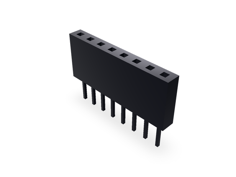
Pin socket (female header): 2.54 mm straight, 2.00 mm surface-mount, 1.27 mm surface-mount and right-angle, 1.00 mm straight and surface-mount, one or two rows.
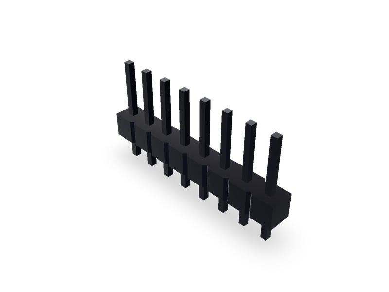
Pin header, 2.54 mm and 2.00 mm pitch in one or two rows, 1.27 mm in two rows, straight or right-angle through-hole, or 1.27 mm surface-mount.