
STEVEMIT
steve/leaded-inductor
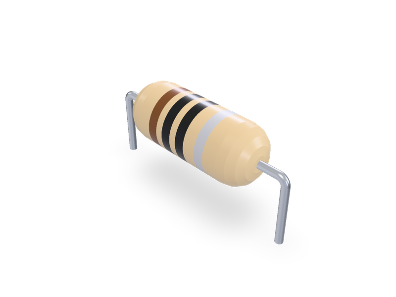
Axial leaded inductor, Fastron fixed choke coils (MICC, SMCC, MECC, HCCC, LACC, HBCC, VHBCC, XHBCC) and suppression coils (MISC, MESC, 77A), Vishay Dale molded IM-1 to IM-10, horizontal or vertical.
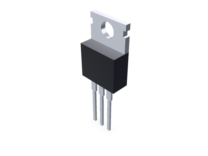
Through-hole TO packages standing on the board: TO-220AB, TO-220AC, TO-220F, TO-247AC, TO-126, TO-92 and the TO-18, TO-39 and TO-46 metal cans, from the makers' drawings.
| 1 | """Through-hole transistor packages standing on the board: TO-220AB (3 leads), TO-220AC (2 leads), TO-247AC (3 leads) and TO-92 (straight |
| 2 | leads). Lead 1 is at the origin, the leads run along +X, the moulded front faces -Y (TO-92: the flat face) and the metal tab or pad is at the |
| 3 | back (+Y). The board is the XY plane: the leads' shoulders (TO-92: the seating plane) rest on it and the leads go down through it. |
| 4 | Dimensions from the makers' package drawings, listed in the README.""" |
| 5 | from steve import Model |
| 6 | import math |
| 7 | |
| 8 | package = "TO-220AB" # TO-220AB, TO-220AC, TO-220F, TO-220F-2, TO-247AC, TO-126, TO-92, TO-18, TO-18-2, TO-39 or TO-46 |
| 9 | detail = "full" # full: body, tab and leads; simple: the body and tab only |
| 10 | |
| 11 | # Vishay Siliconix, "TO-220AB (High Voltage)", Package Information, document 92506, revision 30-Sep-2024 (DWG 6031), page 2 table; and |
| 12 | # Vishay Semiconductors, "TO-220AC", Outline Dimensions, document 95221, revision 16-Jan-2026, table: (min, max) in mm, the model uses the |
| 13 | # middle of each. A body+tab thickness, A1 tab thickness, A2 lead's back face to the tab's back, b lead width, b2 shoulder width, |
| 14 | # c lead thickness, D overall height, D1 moulded body height, D2 metal on the back (from the top), E width, E1 back metal width, E2 tab notch |
| 15 | # depth, e1 lead 1 to the last lead, H1 tab above the body, L lead length, L1 shoulder length, P hole diameter, Q hole centre below the top. |
| 16 | TO220AB = dict(A=(4.25, 4.65), A1=(1.20, 1.34), A2=(2.563, 2.92), b=(0.71, 0.91), b2=(1.14, 1.78), c=(0.46, 0.61), D=(14.32, 15.86), |
| 17 | D1=(8.39, 8.79), D2=(12.20, 12.80), E=(9.96, 10.36), E1=(8.14, 8.74), E2=(0.59, 0.69), e1=(5.08, 5.08), H1=(6.30, 6.70), |
| 18 | L=(13.40, 14.40), L1=(3.65, 4.05), P=(3.60, 3.80), Q=(2.54, 2.94)) |
| 19 | TO220AC = dict(A=(4.25, 4.65), A1=(1.14, 1.40), A2=(2.56, 2.92), b=(0.69, 1.01), b2=(1.20, 1.73), c=(0.36, 0.61), D=(14.85, 15.25), |
| 20 | D1=(8.38, 9.02), D2=(11.68, 12.88), E=(10.11, 10.51), E1=(6.86, 8.89), E2=(0.76, 0.76), e1=(4.88, 5.28), H1=(5.84, 6.86), |
| 21 | L=(13.52, 14.02), L1=(3.32, 3.82), P=(3.54, 3.73), Q=(2.60, 3.00)) |
| 22 | # Vishay Siliconix, "TO-247AC (High Voltage)", Package Information, document 91360, revision 07-Sep-2026, version 1 (facility code 9), |
| 23 | # table (nominal) in mm: A body thickness, A1 back face to the leads' back face, A2 exposed copper (drawn at the back face), b lead width, |
| 24 | # b2 outer shoulders, b4 middle shoulder, c lead thickness, D height, D1 x E1 the exposed copper, D2 its top below the top, E width, E2 side |
| 25 | # slot width, e pitch, L lead length, L1 shoulder length, P hole diameter, P1 copper ring round the hole (ref), Q hole and slots below the top. |
| 26 | TO247AC = dict(A=5.02, A1=2.41, A2=1.27, b=1.20, b2=2.00, b4=3.00, c=0.50, D=20.55, D1=16.76, D2=0.66, E=15.70, E1=14.02, E2=4.91, |
| 27 | e=5.46, L=15.15, L1=4.06, P=3.61, P1=7.19, Q=5.50) |
| 28 | # Texas Instruments, LP0003A "TO-92 - 5.34 mm max height", drawing 4215214/C 04/2025 (ti.com/lit/pdf/msot002), straight lead option: |
| 29 | # (min, max) in mm, the model uses the middle: W body width, H body height, T body depth (round back to flat face), K round back to the leads' |
| 30 | # centre line, F flat face width (min), b lead width, c lead thickness, e pitch (1.27 +/-0.13), L lead length (12.7 min), S the seating plane |
| 31 | # below the body ((1.5) typical, reference). |
| 32 | TO92 = dict(W=(4.44, 5.21), H=(4.32, 5.34), T=(3.17, 4.19), K=(2.03, 2.67), F=(3.43, 3.43), b=(0.38, 0.55), c=(0.35, 0.43), e=(1.27, 1.27), |
| 33 | L=(12.7, 12.7), S=(1.5, 1.5)) |
| 34 | # Central Semiconductor, "Package Details - TO-18" (REV: R1; R0 21-June 2004) and "TO-18 2-Lead Case" (REV: R0; 13-March 2013), table |
| 35 | # (min, max) in mm, the model uses the middle (C: its max, the only value; E: 12.70 min): A flange Ø, B can Ø, C flange thickness, D height, |
| 36 | # E lead length, F lead Ø, G lead circle Ø (3 leads) or lead spacing (2 leads), H lead 2 off the line of leads 1 and 3, I tab width, |
| 37 | # J tab length (read as beyond the flange's edge); the tab is at 45 deg, beside lead 1. |
| 38 | TO18 = dict(A=(5.31, 5.84), B=(4.52, 4.95), C=(0.76, 0.76), D=(4.32, 5.33), E=(12.70, 12.70), F=(0.41, 0.48), G=(2.54, 2.54), H=(1.27, 1.27), |
| 39 | I=(0.91, 1.17), J=(0.71, 1.22)) |
| 40 | # Proportions, for looks (README): the TO-220 tab's side notches are 1.4 high, from 1.4 to 2.8 below the top (as drawn); the TO-220AC's cut-off middle lead isn't |
| 41 | # modelled; the TO-247's side slots are half-round (Ø E2) and the copper ring P1 isn't modelled; the TO-92's flat face is cut from a round body |
| 42 | # W across; every lead's shoulder narrows to the lead in one step. |
| 43 | NOTCH = (1.4, 2.8) |
| 44 | # Central Semiconductor, "Package Details - TO-39" (REV R1, R0 21-June 2004) and "Package Details - TO-46" (REV R2, R0 17-July 2008), tables |
| 45 | # (min, max) in mm, the letters as TO18's (C: the max, the only value; E: 12.70 min). TO-46's sheet names the tab width J and its length K; |
| 46 | # here they are I and J, as on the TO-18 and TO-39 sheets. |
| 47 | TO39 = dict(A=(8.51, 9.40), B=(8.00, 8.51), C=(1.02, 1.02), D=(6.10, 6.60), E=(12.70, 12.70), F=(0.41, 0.53), G=(5.08, 5.08), H=(2.54, 2.54), |
| 48 | I=(0.71, 0.86), J=(0.74, 1.14)) |
| 49 | TO46 = dict(A=(5.31, 5.84), B=(4.52, 4.95), C=(1.02, 1.02), D=(1.65, 2.16), E=(12.70, 12.70), F=(0.41, 0.53), G=(2.54, 2.54), H=(1.27, 1.27), |
| 50 | I=(0.91, 1.17), J=(0.71, 1.22)) |
| 51 | CANS = {"TO-18": TO18, "TO-18-2": TO18, "TO-39": TO39, "TO-46": TO46} |
| 52 | # Central Semiconductor, "Package Details - TO-126" (REV R3, R0 21-June 2004), table (min, max) in mm, the middle (single values as given): |
| 53 | # A body thickness, B the leads' centre plane from the back, C lead thickness, D width, E hole centre below the top, F hole diameter, |
| 54 | # G body height, H lead length below the body (shoulder included), J lead width, K pitch, L lead 1 to lead 3, M shoulder width, N shoulder |
| 55 | # length. The back carries the mounting plate ("Mounting Plate Common to Pin 2"). |
| 56 | TO126 = dict(A=(2.40, 2.80), B=(1.27, 1.27), C=(0.38, 0.75), D=(7.40, 8.50), E=(3.75, 3.75), F=(3.00, 3.40), G=(10.50, 12.00), |
| 57 | H=(15.70, 15.70), J=(0.62, 0.90), K=(2.25, 2.25), L=(4.50, 4.50), M=(1.14, 1.40), N=(2.10, 2.10)) |
| 58 | # Central Semiconductor, "Package Details - TO-220FP Case" (REV R5, R2 06-June 2023) and "TO-220FP-2 Case" (REV R2, R0 28-January 2015), |
| 59 | # tables (min, max) in mm; where a sheet gives only a maximum the model uses it. A body thickness, B the thinner top part's thickness, |
| 60 | # C the leads' centre plane from the back, D lead thickness, E width, F the thin top part's height, G body height, H shoulder length, |
| 61 | # J lead length below the body, K lead width, L pitch (TO-220FP-2: each lead's offset from the centre line), M hole centre below the top, |
| 62 | # N hole diameter, P shoulder width. The fully moulded body has no exposed metal. |
| 63 | TO220F = dict(A=(4.20, 5.12), B=(2.30, 3.30), C=(2.50, 3.10), D=(0.80, 0.80), E=(9.70, 10.63), F=(6.06, 7.00), G=(14.80, 16.25), |
| 64 | H=(4.50, 4.50), J=(12.78, 13.80), K=(0.50, 0.90), L=(2.54, 2.54), M=(2.55, 3.55), N=(2.95, 3.40), P=(1.00, 1.47)) |
| 65 | TO220F2 = dict(A=(4.80, 4.80), B=(3.12, 3.12), C=(2.50, 2.90), D=(0.81, 0.81), E=(10.31, 10.31), F=(6.30, 6.90), G=(14.80, 15.40), |
| 66 | H=(4.10, 4.10), J=(13.00, 13.80), K=(0.90, 0.90), L=(2.55, 2.55), M=(2.55, 2.85), N=(3.00, 3.40), P=(1.40, 1.40)) |
| 67 | # Proportions, for looks: the TO-126's mounting plate on the back is 0.3 thick, set in 0.08 x the width from the sides and the top and |
| 68 | # ending 0.1 x the height above the bottom (drawn dashed in the front view, not dimensioned); the TO-220FP-2's cut-off middle lead stub |
| 69 | # (O, P, Q on its sheet) isn't modelled. |
| 70 | PLATE_T = 0.3 |
| 71 | |
| 72 | PACKAGES = ("TO-220AB", "TO-220AC", "TO-220F", "TO-220F-2", "TO-247AC", "TO-126", "TO-92", "TO-18", "TO-18-2", "TO-39", "TO-46") |
| 73 | if package not in PACKAGES: |
| 74 | raise ValueError("package: " + ", ".join(PACKAGES)) |
| 75 | |
| 76 | |
| 77 | def mid(table): |
| 78 | return {k: (v[0] + v[1]) / 2 if isinstance(v, tuple) else v for k, v in table.items()} |
| 79 | |
| 80 | |
| 81 | model = Model() |
| 82 | |
| 83 | |
| 84 | def box(fid, x0, x1, y0, y1, z0, z1, body, op, name): |
| 85 | model.plane(f"{fid}_plane", on="XY", offset=z0, name=name) |
| 86 | with model.sketch(f"{fid}_sketch", on=f"{fid}_plane", name=name) as sk: |
| 87 | sk.rect(f"{fid}_rect", (x0, y0), (x1, y1)) |
| 88 | model.extrude(fid, f"{fid}_sketch", distance=z1 - z0, op=op, body=body, name=name) |
| 89 | |
| 90 | |
| 91 | def through_y(fid, profile, y0, y1, body, op, name): |
| 92 | """A prism of `profile` (x, z points, or a circle (x, z, r)) from y0 to y1 (y0 > y1: an XZ plane at y0 extrudes along -Y).""" |
| 93 | model.plane(f"{fid}_plane", on="XZ", offset=-y0, name=name) |
| 94 | with model.sketch(f"{fid}_sketch", on=f"{fid}_plane", name=name) as sk: |
| 95 | if len(profile) == 3 and not isinstance(profile[0], tuple): |
| 96 | sk.circle(f"{fid}_circle", (profile[0], profile[1]), profile[2]) |
| 97 | else: |
| 98 | sk.polyline(f"{fid}_outline", profile, closed=True) |
| 99 | model.extrude(fid, f"{fid}_sketch", distance=y0 - y1, op=op, body=body, name=name) |
| 100 | |
| 101 | |
| 102 | def leads(xs, b, c, L, shoulder, widths, top): |
| 103 | """Each lead: its shoulder (width from `widths`) from the body's underside `top` down `shoulder`, then the lead (b x c) to L below it.""" |
| 104 | model.plane("leads_plane", on="XY", offset=top - L, name="Leads") |
| 105 | with model.sketch("leads_sketch", on="leads_plane", name="Leads") as sk: |
| 106 | for i, x in enumerate(xs): |
| 107 | sk.rect(f"lead_{i}", (x - b / 2, -c / 2), (x + b / 2, c / 2)) |
| 108 | model.extrude("leads", "leads_sketch", distance=L - shoulder, op="new", body="leads_body", name="Leads") |
| 109 | model.plane("shoulders_plane", on="XY", offset=top - shoulder, name="Lead shoulders") |
| 110 | with model.sketch("shoulders_sketch", on="shoulders_plane", name="Lead shoulders") as sk: |
| 111 | for i, (x, w) in enumerate(zip(xs, widths)): |
| 112 | sk.rect(f"shoulder_{i}", (x - w / 2, -c / 2), (x + w / 2, c / 2)) |
| 113 | model.extrude("shoulders", "shoulders_sketch", distance=shoulder, op="join", body="leads_body", name="Lead shoulders") |
| 114 | |
| 115 | |
| 116 | bodies = {} |
| 117 | if package in ("TO-220AB", "TO-220AC"): |
| 118 | t = mid(TO220AB if package == "TO-220AB" else TO220AC) |
| 119 | xs = [0.0, t["e1"] / 2, t["e1"]] if package == "TO-220AB" else [0.0, t["e1"]] |
| 120 | cx = t["e1"] / 2 |
| 121 | back = t["c"] / 2 + t["A2"] |
| 122 | front = back - t["A"] |
| 123 | z0 = t["L1"] # the shoulders rest on the board |
| 124 | top = z0 + t["D"] |
| 125 | E, E1 = t["E"], t["E1"] |
| 126 | # Moulded body, with the back recessed where the metal shows (E1 wide, from the body's top down to D2 below the package's top). |
| 127 | box("body", cx - E / 2, cx + E / 2, front, back, z0, z0 + t["D1"], "body_body", "new", "Body") |
| 128 | box("back_recess", cx - E1 / 2, cx + E1 / 2, back - t["A1"], back, top - t["D2"], z0 + t["D1"], "body_body", "cut", "Back metal recess") |
| 129 | # Metal tab: E wide above the body, E1 wide down the back; side notches E2 deep at the hole; the hole P at Q below the top. |
| 130 | box("tab", cx - E / 2, cx + E / 2, back - t["A1"], back, z0 + t["D1"], top, "tab_body", "new", "Tab") |
| 131 | box("tab_back", cx - E1 / 2, cx + E1 / 2, back - t["A1"], back, top - t["D2"], z0 + t["D1"], "tab_body", "join", "Tab") |
| 132 | zq = top - t["Q"] |
| 133 | for side, x0 in (("left", cx - E / 2), ("right", cx + E / 2 - t["E2"])): |
| 134 | box(f"notch_{side}", x0, x0 + t["E2"], back - t["A1"], back, top - NOTCH[1], top - NOTCH[0], "tab_body", "cut", "Tab notch") |
| 135 | through_y("tab_hole", (cx, zq, t["P"] / 2), back + 0.1, back - t["A1"] - 0.1, "tab_body", "cut", "Mounting hole") |
| 136 | bodies = {"body_body": ("pa6", "#1c1c1e"), "tab_body": ("copper", "#c8ccd0")} |
| 137 | if detail == "full": |
| 138 | leads(xs, t["b"], t["c"], t["L"], t["L1"], [t["b2"]] * len(xs), z0) |
| 139 | elif package in ("TO-220F", "TO-220F-2"): |
| 140 | # Fully moulded (no exposed metal): the full thickness A up to F below the top, then the thinner top part B thick, its back face flush. |
| 141 | t = mid(TO220F if package == "TO-220F" else TO220F2) |
| 142 | xs = [0.0, t["L"], 2 * t["L"]] if package == "TO-220F" else [0.0, 2 * t["L"]] |
| 143 | cx = xs[-1] / 2 |
| 144 | back = t["C"] |
| 145 | front = back - t["A"] |
| 146 | z0 = t["H"] # the shoulders rest on the board |
| 147 | top = z0 + t["G"] |
| 148 | E = t["E"] |
| 149 | box("body", cx - E / 2, cx + E / 2, front, back, z0, top - t["F"], "body_body", "new", "Body") |
| 150 | box("body_top", cx - E / 2, cx + E / 2, back - t["B"], back, top - t["F"], top, "body_body", "join", "Body") |
| 151 | through_y("hole", (cx, top - t["M"], t["N"] / 2), back + 0.1, back - t["B"] - 0.1, "body_body", "cut", "Mounting hole") |
| 152 | bodies = {"body_body": ("pa6", "#1c1c1e")} |
| 153 | if detail == "full": |
| 154 | leads(xs, t["K"], t["D"], t["J"], t["H"], [t["P"]] * len(xs), z0) |
| 155 | elif package == "TO-126": |
| 156 | # Moulded body with the mounting plate on its back and the hole through both; leads at pitch K, their centre plane B in front of the back. |
| 157 | t = mid(TO126) |
| 158 | xs = [0.0, t["K"], 2 * t["K"]] |
| 159 | cx = t["K"] |
| 160 | back = t["B"] |
| 161 | front = back - t["A"] |
| 162 | z0 = t["N"] |
| 163 | top = z0 + t["G"] |
| 164 | W = t["D"] |
| 165 | box("body", cx - W / 2, cx + W / 2, front, back, z0, top, "body_body", "new", "Body") |
| 166 | m = 0.08 * W |
| 167 | box("plate_recess", cx - W / 2 + m, cx + W / 2 - m, back - PLATE_T, back, z0 + 0.1 * t["G"], top - m, "body_body", "cut", "Plate recess") |
| 168 | box("plate", cx - W / 2 + m, cx + W / 2 - m, back - PLATE_T, back, z0 + 0.1 * t["G"], top - m, "plate_body", "new", "Mounting plate") |
| 169 | through_y("hole", (cx, top - t["E"], t["F"] / 2), back + 0.1, front - 0.1, "body_body", "cut", "Mounting hole") |
| 170 | through_y("plate_hole", (cx, top - t["E"], t["F"] / 2), back + 0.1, front - 0.1, "plate_body", "cut", "Mounting hole") |
| 171 | bodies = {"body_body": ("pa6", "#1c1c1e"), "plate_body": ("copper", "#c8ccd0")} |
| 172 | if detail == "full": |
| 173 | leads(xs, t["J"], t["C"], t["H"], t["N"], [t["M"]] * 3, z0) |
| 174 | elif package == "TO-247AC": |
| 175 | t = TO247AC |
| 176 | xs = [0.0, t["e"], 2 * t["e"]] |
| 177 | cx = t["e"] |
| 178 | back = t["c"] / 2 + t["A1"] |
| 179 | front = back - t["A"] |
| 180 | z0 = t["L1"] |
| 181 | top = z0 + t["D"] |
| 182 | E = t["E"] |
| 183 | box("body", cx - E / 2, cx + E / 2, front, back, z0, top, "body_body", "new", "Body") |
| 184 | zq = top - t["Q"] |
| 185 | for side, x in (("left", cx - E / 2), ("right", cx + E / 2)): |
| 186 | through_y(f"slot_{side}", (x, zq, t["E2"] / 2), back + 0.1, front - 0.1, "body_body", "cut", "Side slot") |
| 187 | # Exposed copper on the back, flush: D1 x E1 from D2 below the top, A2 thick, with the hole through it. |
| 188 | box("pad_recess", cx - t["E1"] / 2, cx + t["E1"] / 2, back - t["A2"], back, top - t["D2"] - t["D1"], top - t["D2"], "body_body", "cut", "Copper recess") |
| 189 | box("pad", cx - t["E1"] / 2, cx + t["E1"] / 2, back - t["A2"], back, top - t["D2"] - t["D1"], top - t["D2"], "pad_body", "new", "Exposed copper") |
| 190 | through_y("hole", (cx, zq, t["P"] / 2), back + 0.1, front - 0.1, "body_body", "cut", "Mounting hole") |
| 191 | through_y("pad_hole", (cx, zq, t["P"] / 2), back + 0.1, front - 0.1, "pad_body", "cut", "Mounting hole") |
| 192 | for side, x in (("left", cx - E / 2), ("right", cx + E / 2)): |
| 193 | through_y(f"pad_slot_{side}", (x, zq, t["E2"] / 2), back + 0.1, front - 0.1, "pad_body", "cut", "Side slot") |
| 194 | bodies = {"body_body": ("pa6", "#1c1c1e"), "pad_body": ("copper", "#c8ccd0")} |
| 195 | if detail == "full": |
| 196 | leads(xs, t["b"], t["c"], t["L"], t["L1"], [t["b2"], t["b4"], t["b2"]], z0) |
| 197 | elif package in CANS: |
| 198 | # Metal can: the flange (header) on the board, the can on it; leads on a circle round the axis (lead 1 at the origin, lead 3 or lead 2 |
| 199 | # at +X by G, the 3-lead part's lead 2 H off that line along -Y); the tab at 45 deg toward -X +Y, beside lead 1. |
| 200 | t = mid(CANS[package]) |
| 201 | cx = t["G"] / 2 |
| 202 | xs = [(0.0, 0.0), (t["G"], 0.0)] if package == "TO-18-2" else [(0.0, 0.0), (cx, -t["H"]), (t["G"], 0.0)] |
| 203 | model.plane("flange_plane", on="XY", offset=0.0, name="Flange") |
| 204 | with model.sketch("flange_sketch", on="flange_plane", name="Flange") as sk: |
| 205 | sk.circle("flange_round", (cx, 0.0), t["A"] / 2) |
| 206 | u = (-math.sqrt(0.5), math.sqrt(0.5)) |
| 207 | v = (u[1], -u[0]) |
| 208 | r0, r1, w = t["A"] / 2 - 0.3, t["A"] / 2 + t["J"], t["I"] / 2 |
| 209 | sk.polyline("tab_outline", [(cx + u[0] * r + v[0] * s, u[1] * r + v[1] * s) for r, s in ((r0, -w), (r1, -w), (r1, w), (r0, w))], closed=True) |
| 210 | model.extrude("flange", "flange_sketch", distance=t["C"], op="new", body="header_body", name="Flange and tab") |
| 211 | model.plane("can_plane", on="XY", offset=t["C"], name="Can") |
| 212 | with model.sketch("can_sketch", on="can_plane", name="Can") as sk: |
| 213 | sk.circle("can_round", (cx, 0.0), t["B"] / 2) |
| 214 | model.extrude("can", "can_sketch", distance=t["D"] - t["C"], op="new", body="can_body", name="Can") |
| 215 | bodies = {"header_body": ("nickel", "#c9ccd1"), "can_body": ("steel-dc01", "#d5d8dc")} |
| 216 | if detail == "full": |
| 217 | model.plane("leads_plane", on="XY", offset=-t["E"], name="Leads") |
| 218 | with model.sketch("leads_sketch", on="leads_plane", name="Leads") as sk: |
| 219 | for i, (x, y) in enumerate(xs): |
| 220 | sk.circle(f"lead_{i}", (x, y), t["F"] / 2) |
| 221 | model.extrude("leads", "leads_sketch", distance=t["E"], op="new", body="leads_body", name="Leads") |
| 222 | else: |
| 223 | t = mid(TO92) |
| 224 | xs = [0.0, t["e"], 2 * t["e"]] |
| 225 | cx = t["e"] |
| 226 | R = t["W"] / 2 |
| 227 | yc = t["K"] - R # the round body's axis: K from the round back to the leads, so the back is at +K |
| 228 | flat = t["K"] - t["T"] # the flat face (-Y) |
| 229 | z0 = t["S"] |
| 230 | n = 24 |
| 231 | a0 = math.asin(max(-1.0, min(1.0, (flat - yc) / R))) |
| 232 | pts = [(cx + R * math.cos(a), yc + R * math.sin(a)) for a in (a0 + (math.pi - 2 * a0) * k / n for k in range(n + 1))] |
| 233 | model.plane("body_plane", on="XY", offset=z0, name="Body") |
| 234 | with model.sketch("body_sketch", on="body_plane", name="Body") as sk: |
| 235 | sk.polyline("body_outline", [(cx + R * math.cos(a0), flat)] + pts[1:-1] + [(cx - R * math.cos(a0), flat)], closed=True) |
| 236 | model.extrude("body", "body_sketch", distance=t["H"], op="new", body="body_body", name="Body") |
| 237 | bodies = {"body_body": ("pa6", "#1c1c1e")} |
| 238 | if detail == "full": |
| 239 | model.plane("leads_plane", on="XY", offset=z0 - t["L"], name="Leads") |
| 240 | with model.sketch("leads_sketch", on="leads_plane", name="Leads") as sk: |
| 241 | for i, x in enumerate(xs): |
| 242 | sk.rect(f"lead_{i}", (x - t["b"] / 2, -t["c"] / 2), (x + t["b"] / 2, t["c"] / 2)) |
| 243 | model.extrude("leads", "leads_sketch", distance=t["L"], op="new", body="leads_body", name="Leads") |
| 244 | if detail == "full": |
| 245 | bodies["leads_body"] = ("nickel", "#d8c58a") if package in CANS else ("copper", "#c9ccd1") |
| 246 | # Materials, for looks and a rough mass: the moulding is epoxy (nylon, PA6, the nearest in the list), the tab and pad copper (nickel or tin |
| 247 | # plated), the leads tinned copper. TO-18 (Central's material sheets): the header and leads Kovar (density 8.36; nickel, 8.9, is the nearest |
| 248 | # in the list), the can a nickel-plated iron alloy (steel). |
| 249 | for body, (material, colour) in bodies.items(): |
| 250 | model.material(material, bodies=[body], color=colour) |
| 251 | result = model.result() |
| 252 |
| 1 | name = "steve/to-package" |
| 2 | version = "1.1.0" |
| 3 | runtime = "steve" |
| 4 | license = "MIT" |
| 5 | summary = "Through-hole TO packages standing on the board: TO-220AB, TO-220AC, TO-220F, TO-247AC, TO-126, TO-92 and the TO-18, TO-39 and TO-46 metal cans, from the makers' drawings." |
| 6 | description = """A through-hole transistor, regulator or diode package standing on the board, from the maker's package drawing: TO-220AB (3 leads) and TO-220AC (2 leads) with the metal tab and its hole, TO-247AC with its exposed copper and side slots, TO-92 with straight leads, TO-126 with its mounting plate, the fully moulded TO-220F with 3 or 2 leads, and the TO-18 (2 or 3 leads), TO-39 and TO-46 metal cans. Lead 1 at the origin, the leads along +X, the moulded front toward -Y. See the README.""" |
| 7 | tags = ["to-220", "to-247", "to-92", "to-18", "to-39", "to-126", "transistor", "package", "through-hole", "electronics"] |
| 8 | |
| 9 | [parameters.package] |
| 10 | type = "choice" |
| 11 | default = "TO-220AB" |
| 12 | choices = ["TO-220AB", "TO-220AC", "TO-220F", "TO-220F-2", "TO-247AC", "TO-126", "TO-92", "TO-18", "TO-18-2", "TO-39", "TO-46"] |
| 13 | label = "Package" |
| 14 | description = "TO-220AB: 3 leads at 2.54. TO-220AC: 2 leads 5.08 apart. TO-247AC: 3 leads at 5.46. TO-92: 3 straight leads at 1.27. TO-18: metal can, 3 leads on a 2.54 circle; TO-18-2: 2 leads 2.54 apart. TO-39: metal can, Ø 9, 3 leads on a 5.08 circle. TO-46: low metal can, 3 leads on a 2.54 circle. TO-126: 3 leads at 2.25, mounting plate on the back. TO-220F: fully moulded, 3 leads at 2.54; TO-220F-2: 2 leads 5.1 apart." |
| 15 | |
| 16 | [parameters.detail] |
| 17 | type = "choice" |
| 18 | default = "full" |
| 19 | choices = ["full", "simple"] |
| 20 | label = "Detail" |
| 21 | description = "full: body, tab and leads. simple: the body and tab only, for big assemblies." |
| 22 | |
| 23 | [[presets]] |
| 24 | id = "TO-220AB" |
| 25 | title = "TO-220AB, 3 leads, 2.54 pitch, vertical (Vishay outline)" |
| 26 | params = { package = "TO-220AB" } |
| 27 | aliases = ["TO-220-3", "TO-220", "TO-220AB", "JEDEC TO-220AB", "TO220 3 lead"] |
| 28 | standard = "Vishay TO-220AB" |
| 29 | |
| 30 | [[presets]] |
| 31 | id = "TO-220AC" |
| 32 | title = "TO-220AC, 2 leads, 5.08 apart, vertical (Vishay outline)" |
| 33 | params = { package = "TO-220AC" } |
| 34 | aliases = ["TO-220-2", "TO-220AC", "JEDEC TO-220AC", "TO220 2 lead"] |
| 35 | standard = "Vishay TO-220AC" |
| 36 | |
| 37 | [[presets]] |
| 38 | id = "TO-220F" |
| 39 | title = "TO-220F (fully moulded), 3 leads, 2.54 pitch, vertical (Central Semiconductor outline)" |
| 40 | params = { package = "TO-220F" } |
| 41 | aliases = ["TO-220F-3", "TO-220F", "TO-220FP", "TO-220 FullPAK", "TO-220 full pack 3 lead"] |
| 42 | standard = "Central TO-220FP" |
| 43 | |
| 44 | [[presets]] |
| 45 | id = "TO-220F-2" |
| 46 | title = "TO-220F (fully moulded), 2 leads, 5.1 apart, vertical (Central Semiconductor outline)" |
| 47 | params = { package = "TO-220F-2" } |
| 48 | aliases = ["TO-220F-2", "TO-220FP-2", "TO-220 full pack 2 lead"] |
| 49 | standard = "Central TO-220FP-2" |
| 50 | |
| 51 | [[presets]] |
| 52 | id = "TO-247AC" |
| 53 | title = "TO-247AC, 3 leads, 5.46 pitch, vertical (Vishay outline)" |
| 54 | params = { package = "TO-247AC" } |
| 55 | aliases = ["TO-247-3", "TO-247", "TO-247AC", "JEDEC TO-247AC", "TO247 3 lead"] |
| 56 | standard = "Vishay TO-247AC" |
| 57 | |
| 58 | [[presets]] |
| 59 | id = "TO-126" |
| 60 | title = "TO-126, 3 leads, 2.25 pitch, vertical (Central Semiconductor outline)" |
| 61 | params = { package = "TO-126" } |
| 62 | aliases = ["TO-126-3", "TO-126", "TO126 3 lead", "SOT-32"] |
| 63 | standard = "Central TO-126" |
| 64 | |
| 65 | [[presets]] |
| 66 | id = "TO-92" |
| 67 | title = "TO-92, 3 straight leads, 1.27 pitch (TI LP0003A)" |
| 68 | params = { package = "TO-92" } |
| 69 | aliases = ["TO-92-3", "TO-92", "TO-226AA", "JEDEC TO-226AA", "TO92 straight leads", "LP0003A", "TO-92, 3 straight leads, 1.27 pitch (TI LP0003A)"] |
| 70 | standard = "TI LP0003A" |
| 71 | |
| 72 | [[presets]] |
| 73 | id = "TO-18" |
| 74 | title = "TO-18 metal can, 3 leads (Central Semiconductor outline)" |
| 75 | params = { package = "TO-18" } |
| 76 | aliases = ["TO-18-3", "TO-18", "TO-206AA", "JEDEC TO-206AA", "TO18 metal can 3 lead"] |
| 77 | standard = "Central TO-18" |
| 78 | |
| 79 | [[presets]] |
| 80 | id = "TO-18-2" |
| 81 | title = "TO-18 metal can, 2 leads (Central Semiconductor outline)" |
| 82 | params = { package = "TO-18-2" } |
| 83 | aliases = ["TO-18-2", "TO-18 2 lead", "TO18 metal can 2 lead"] |
| 84 | standard = "Central TO-18 2-lead" |
| 85 | |
| 86 | [[presets]] |
| 87 | id = "TO-39" |
| 88 | title = "TO-39 metal can, 3 leads (Central Semiconductor outline)" |
| 89 | params = { package = "TO-39" } |
| 90 | aliases = ["TO-39-3", "TO-39", "TO-205AD", "JEDEC TO-205AD", "TO39 metal can 3 lead"] |
| 91 | standard = "Central TO-39" |
| 92 | |
| 93 | [[presets]] |
| 94 | id = "TO-46" |
| 95 | title = "TO-46 metal can, 3 leads (Central Semiconductor outline)" |
| 96 | params = { package = "TO-46" } |
| 97 | aliases = ["TO-46-3", "TO-46", "TO-206AB", "JEDEC TO-206AB", "TO46 metal can 3 lead"] |
| 98 | standard = "Central TO-46" |
| 99 | |
| 100 | [[presets]] |
| 101 | id = "TO-220AB-simple" |
| 102 | title = "TO-220AB, 3 leads, 2.54 pitch, vertical (Vishay outline), simple" |
| 103 | params = { package = "TO-220AB", detail = "simple" } |
| 104 | aliases = ["TO-220AB simple"] |
| 105 | standard = "Vishay TO-220AB" |
| 106 |
A through-hole transistor, regulator or diode package standing on the board, built from the maker's package drawing. These are the JEDEC outlines that every maker builds:
package |
Leads | Body (W x thickness x height) | Source |
|---|---|---|---|
TO-220AB |
3, 2.54 pitch | 10.16 x 4.45 x 15.09 (tab included) | Vishay Siliconix 92506 |
TO-220AC |
2, 5.08 apart | 10.31 x 4.45 x 15.05 (tab included) | Vishay Semiconductors 95221 |
TO-220F |
3, 2.54 pitch | 10.17 x 4.66 x 15.53, fully moulded | Central Semiconductor TO-220FP |
TO-220F-2 |
2, 5.10 apart | 10.31 x 4.80 x 15.10, fully moulded | Central Semiconductor TO-220FP-2 |
TO-247AC |
3, 5.46 pitch | 15.70 x 5.02 x 20.55 | Vishay Siliconix 91360 |
TO-126 |
3, 2.25 pitch | 7.95 x 2.60 x 11.25 | Central Semiconductor TO-126 |
TO-92 |
3 straight, 1.27 pitch | 4.83 x 3.68 x 4.83 | TI LP0003A |
TO-18 |
3, on a Ø 2.54 circle | flange Ø 5.58, can Ø 4.74, 4.83 high | Central Semiconductor TO-18 |
TO-18-2 |
2, 2.54 apart | as TO-18 |
Central Semiconductor TO-18 2-Lead |
TO-39 |
3, on a Ø 5.08 circle | flange Ø 8.96, can Ø 8.26, 6.35 high | Central Semiconductor TO-39 |
TO-46 |
3, on a Ø 2.54 circle | flange Ø 5.58, can Ø 4.74, 1.91 high | Central Semiconductor TO-46 |
Lead 1 is at the origin and the leads run along +X. The moulded front faces -Y (on the TO-92, the flat face), and the metal tab, exposed copper or mounting plate is at the back (+Y).
detail = "simple" leaves out the leads.
Each table gives a minimum and a maximum. The part uses the middle of the two, except where noted. part.py holds every table as read.
How the letters are read:
Proportions, for looks only. The drawings show these but don't dimension them:
The reference models were measured against the drawings, and each falls inside the drawing's tolerances:
Added in 1.1.0, measured the same way:
The names name the JEDEC package, so they map to the maker's drawing of it, with the pitch and lead order as named, and the differences are listed here.
The reference models stand their bodies at different heights above the board: the TO-92 at 2.5, and the TO-18, TO-39 and TO-46 at about 5. The drawings don't give these, so this part uses the drawings' own seating.
So these map: TO-220-3_Vertical (TO-220AB), TO-220-2_Vertical (TO-220AC), TO-247-3_Vertical (TO-247AC), TO-92 and TO-92_Inline (TO-92), TO-18-3 (TO-18), TO-18-2 (TO-18-2), TO-39-3 (TO-39), TO-46-3 (TO-46), TO-126-3_Vertical (TO-126), TO-220F-3_Vertical (TO-220F) and TO-220F-2_Vertical (TO-220F-2).
These stay "no table read yet" (COVERAGE.md):
_Wide). TI's formed leads are 2.4 to 2.9 apart, with a land pattern of 2.6.| 1 | # TO package (through-hole) |
| 2 | |
| 3 | A through-hole transistor, regulator or diode package standing on the board, built from the maker's package drawing. These are the JEDEC outlines that every maker builds: |
| 4 | |
| 5 | | `package` | Leads | Body (W x thickness x height) | Source | |
| 6 | |---|---|---|---| |
| 7 | | `TO-220AB` | 3, 2.54 pitch | 10.16 x 4.45 x 15.09 (tab included) | Vishay Siliconix 92506 | |
| 8 | | `TO-220AC` | 2, 5.08 apart | 10.31 x 4.45 x 15.05 (tab included) | Vishay Semiconductors 95221 | |
| 9 | | `TO-220F` | 3, 2.54 pitch | 10.17 x 4.66 x 15.53, fully moulded | Central Semiconductor TO-220FP | |
| 10 | | `TO-220F-2` | 2, 5.10 apart | 10.31 x 4.80 x 15.10, fully moulded | Central Semiconductor TO-220FP-2 | |
| 11 | | `TO-247AC` | 3, 5.46 pitch | 15.70 x 5.02 x 20.55 | Vishay Siliconix 91360 | |
| 12 | | `TO-126` | 3, 2.25 pitch | 7.95 x 2.60 x 11.25 | Central Semiconductor TO-126 | |
| 13 | | `TO-92` | 3 straight, 1.27 pitch | 4.83 x 3.68 x 4.83 | TI LP0003A | |
| 14 | | `TO-18` | 3, on a Ø 2.54 circle | flange Ø 5.58, can Ø 4.74, 4.83 high | Central Semiconductor TO-18 | |
| 15 | | `TO-18-2` | 2, 2.54 apart | as `TO-18` | Central Semiconductor TO-18 2-Lead | |
| 16 | | `TO-39` | 3, on a Ø 5.08 circle | flange Ø 8.96, can Ø 8.26, 6.35 high | Central Semiconductor TO-39 | |
| 17 | | `TO-46` | 3, on a Ø 2.54 circle | flange Ø 5.58, can Ø 4.74, 1.91 high | Central Semiconductor TO-46 | |
| 18 | |
| 19 | Lead 1 is at the origin and the leads run along +X. The moulded front faces -Y (on the TO-92, the flat face), and the metal tab, exposed copper or mounting plate is at the back (+Y). |
| 20 | |
| 21 | - **TO-220, TO-220F, TO-247 and TO-126.** The leads' shoulders rest on the board (the XY plane), and the leads continue their full length down through it. |
| 22 | - **TO-92.** The body sits 1.5 above the board (TI's reference seating plane). |
| 23 | - **TO-18, TO-39 and TO-46.** The flange sits on the board. Leads 1 and 3 are G apart along +X (2.54, or 5.08 on the TO-39), and lead 2 is H off that line along -Y (1.27, or 2.54). The tab is at 45°, beside lead 1. |
| 24 | |
| 25 | `detail = "simple"` leaves out the leads. |
| 26 | |
| 27 | ## Source |
| 28 | |
| 29 | Each table gives a minimum and a maximum. The part uses the middle of the two, except where noted. `part.py` holds every table as read. |
| 30 | |
| 31 | - **Vishay Siliconix, "TO-220AB (High Voltage)"**, Package Information, document 92506, revision 30-Sep-2024 (DWG 6031), from vishay.com. |
| 32 | - Page 1, drawing: front, side and back views and section F-F. |
| 33 | - Page 2, table (mm): A 4.25–4.65, A1 1.20–1.34, A2 2.563–2.92, b 0.71–0.91, b2 1.14–1.78, c 0.46–0.61, D 14.32–15.86, D1 8.39–8.79, D2 12.20–12.80, E 9.96–10.36, E1 8.14–8.74, E2 0.59–0.69, e 2.54, e1 5.08, H1 6.30–6.70, L 13.40–14.40, L1 3.65–4.05, ØP 3.60–3.80, Q 2.54–2.94. |
| 34 | - **Vishay Semiconductors, "TO-220AC"**, Outline Dimensions, document 95221, revision 16-Jan-2026, from vishay.com. The drawing and table use the same letters. Here e1 is 4.88–5.28, the spacing of the two leads, and E2 is 0.76 max. The outline conforms to JEDEC TO-220AC. |
| 35 | - **Vishay Siliconix, "TO-247AC (High Voltage)"**, Package Information, document 91360, revision 07-Sep-2026, from vishay.com. The part uses version 1 (facility code 9) with its nominal values: |
| 36 | - A 5.02, A1 2.41, A2 1.27, b 1.20, b2 2.00, b4 3.00, c 0.50, D 20.55, D1 16.76, D2 0.66, E 15.70, E1 14.02, E2 4.91, e 5.46, L 15.15, L1 4.06, ØP 3.61, ØP1 7.19 (ref), Q 5.50. |
| 37 | - The package reference is JEDEC TO-247, variation AC. |
| 38 | - **Texas Instruments, LP0003A "TO-92 - 5.34 mm max height"**, drawing 4215214/C 04/2025 (ti.com/lit/pdf/msot002), straight lead option, page 1: |
| 39 | - body 4.44–5.21 wide, 4.32–5.34 high and 3.17–4.19 deep; |
| 40 | - the round back 2.03–2.67 from the leads, and the flat face at least 3.43 wide; |
| 41 | - leads 0.38–0.55 x 0.35–0.43, at 1.27 ±0.13 pitch, 12.7 min long; |
| 42 | - the seating plane (1.5) typical below the body; |
| 43 | - reference JEDEC TO-226, variation AA. |
| 44 | - **Central Semiconductor, "Package Details - TO-18"** (REV R1, R0 21-June 2004) and **"TO-18 2-Lead Case"** (REV R0, 13-March 2013), from centralsemi.com. |
| 45 | - Table (mm): A flange Ø 5.31–5.84, B can Ø 4.52–4.95, C flange 0.76 max (used as is), D height 4.32–5.33, E lead length 12.70 min (used as is), F lead Ø 0.41–0.48, G 2.54 (the lead circle, or the 2-lead part's spacing), H 1.27 (3 leads), and tab width 0.91–1.17 and tab length 0.71–1.22 at 45° (I and J; on the 2-lead sheet, H and J). |
| 46 | - Both sheets' material sheets give a Kovar header and leads and a nickel-plated iron-alloy can. |
| 47 | - **Central Semiconductor, "Package Details - TO-39"** (REV R1, R0 21-June 2004) and **"Package Details - TO-46"** (REV R2, R0 17-July 2008), from centralsemi.com. The tables use the TO-18 sheet's letters: |
| 48 | - TO-39 (mm): A flange Ø 8.51–9.40, B can Ø 8.00–8.51, C flange 1.02 max (used as is), D height 6.10–6.60, E lead length 12.70 min (used as is), F lead Ø 0.41–0.53, G 5.08 (the lead circle), H 2.54, I tab width 0.71–0.86, J tab length 0.74–1.14. |
| 49 | - TO-46 (mm): A 5.31–5.84, B 4.52–4.95, C 1.02 max, D 1.65–2.16, E 12.70 min, F 0.41–0.53, G 2.54, H 1.27, and the tab width 0.91–1.17 and length 0.71–1.22 (its J and K). |
| 50 | - **Central Semiconductor, "Package Details - TO-126"** (REV R3, R0 21-June 2004), from centralsemi.com. Table (mm): A thickness 2.40–2.80, B the leads' centre plane 1.27 from the back, C lead thickness 0.38–0.75, D width 7.40–8.50, E hole centre 3.75 below the top, F hole Ø 3.00–3.40, G body height 10.50–12.00, H lead length 15.70 below the body, J lead width 0.62–0.90, K pitch 2.25 (L 4.50 from lead 1 to lead 3), M shoulder width 1.14–1.40, N shoulder length 2.10. "Mounting Plate Common to Pin 2", on the back. |
| 51 | - **Central Semiconductor, "Package Details - TO-220FP Case"** (REV R5, R2 06-June 2023) and **"TO-220FP-2 Case"** (REV R2, R0 28-January 2015), from centralsemi.com. |
| 52 | - TO-220FP (mm): A thickness 4.20–5.12, B the top part's thickness 2.30–3.30, C the leads' centre plane 2.50–3.10 from the back, D lead thickness 0.80 max, E width 9.70–10.63, F the top part's height 6.06–7.00, G body height 14.80–16.25, H shoulder length 4.50 max, J lead length 12.78–13.80, K lead width 0.50–0.90, L pitch 2.54, M hole centre 2.55–3.55 below the top, N hole Ø 2.95–3.40, P shoulder width 1.00–1.47. |
| 53 | - TO-220FP-2 (mm): A 4.80 max, B 3.12 max, C 2.50–2.90, D 0.81 max, E 10.31 max, F 6.30–6.90, G 14.80–15.40, H 4.10 max, J 13.00–13.80, K 0.90 max, L 2.55 (each lead from the centre line, so 5.10 apart), M 2.55–2.85, N 3.00–3.40, P 1.40 max. Where the sheets give only a maximum, the part uses it. |
| 54 | |
| 55 | How the letters are read: |
| 56 | |
| 57 | - **TO-220 and TO-247.** A2 (TO-247: A1) runs from the leads' back face to the back of the package. The leads' shoulders (b2, b4) are L1 long. On the TO-220, the metal tab is A1 thick: E wide above the moulding (H1 = D - D1), and E1 wide down the back to D2 below the top. On the TO-247, the exposed copper (D1 x E1, from D2 below the top) is taken as A2 thick, the dimension drawn at the back face. The TO-247's side slots are Ø E2, at Q below the top, the same height as the hole. |
| 58 | - **TO-92.** The body is a round of Ø W, cut flat at the depth T, with the leads K in front of the round back. |
| 59 | - **TO-18, TO-39 and TO-46.** The tab length J is read as reaching beyond the flange's edge. |
| 60 | - **TO-220F.** The side view draws the body A thick up to F below the top, and above that B thick with the back face flush, so the hole is in the thinner part. H is the shoulder's length below the body, J the lead's from the body. |
| 61 | - **TO-126.** H is the lead's length from the body, shoulder included, and B runs from the back (the side the sheet marks "BACKSIDE") to the leads' centre plane. |
| 62 | |
| 63 | **Proportions, for looks only.** The drawings show these but don't dimension them: |
| 64 | |
| 65 | - The TO-220 tab's side notches, E2 deep, are 1.4 high, from 1.4 to 2.8 below the top, as drawn. |
| 66 | - The TO-126's mounting plate on the back, drawn dashed in the front view, is 0.3 thick, set in 0.08 x the width from the sides and the top, and ends 0.1 x the height above the bottom. |
| 67 | - Not modelled: the TO-220AC's and TO-220FP-2's cut-off middle lead, the TO-220's ejector dimple, the TO-247's copper ring ØP1, and the bodies' 5° draft and small radii. |
| 68 | - Every lead's shoulder narrows to the lead in one step. |
| 69 | - Materials are for looks and a rough mass: |
| 70 | - The mouldings are epoxy. Nylon (PA6) is the nearest material in the list. |
| 71 | - The TO-220 tab, the TO-247 pad and the TO-126 plate are copper, and the leads are tinned copper. |
| 72 | - The TO-18, TO-39 and TO-46 headers and leads are Kovar (8.36), so nickel (8.9), the nearest in the list. Their cans are steel. |
| 73 | |
| 74 | ## Catalogue models |
| 75 | |
| 76 | The reference models were measured against the drawings, and each falls inside the drawing's tolerances: |
| 77 | |
| 78 | - **TO-220-3_Vertical.** 10.26 wide, 4.46 thick and 15.07 high with the tab. Leads 0.86 x 0.53 with 1.46 shoulders at 2.54. The leads' back face is 2.90 from the back. |
| 79 | - **TO-220-2_Vertical.** The same body, with leads at 0 and 5.08. |
| 80 | - **TO-247-3_Vertical.** 15.90 wide (E max 15.87, so 0.03 over), 5.03 thick and 20.7 high. Leads 1.20 with shoulders 2.03 and 3.00 at 5.45. |
| 81 | - **TO-92 and TO-92_Inline.** 4.83 wide, 3.75 deep. Leads at 1.27, with the flat face 1.33 in front of the leads and the round back 2.42 behind them. |
| 82 | - **TO-18-3.** Flange Ø 5.84, can Ø 4.95 and leads Ø 0.48 (the drawing's maximums). Lead 2 is 1.27 off the line of leads 1 and 3, and the tab is at 45° beside lead 1. |
| 83 | |
| 84 | Added in 1.1.0, measured the same way: |
| 85 | |
| 86 | - **TO-39-3.** Flange Ø 9.40 and can Ø 8.50 (the drawing's maximums), 6.5 high, leads Ø 0.48 on a Ø 5.08 circle with lead 2 2.54 off the line. The model has no tab; the drawing has one. |
| 87 | - **TO-46-3.** Flange Ø 5.84 with the 45° tab, can Ø 4.80 tapering to 4.73, 2.2 high (D max 2.16, so 0.04 over), leads Ø 0.48 on a Ø 2.54 circle with lead 2 1.27 off the line. |
| 88 | - **TO-126-3_Vertical.** 8.0 wide and 11.0 high, as drawn, but 3.25 thick where Central's drawing allows 2.40–2.80 (0.45 over). Leads 0.75 x 0.53 at 2.28 (Central 2.25, so 0.03 apart), their plane 1.25 from the back. Only the middle lead has a shoulder (1.6 wide), where Central draws one on every lead, 1.14–1.40 wide. |
| 89 | - **TO-220F-3_Vertical.** 10.16 wide, 4.70 thick, with the top part 2.54 thick, and 15.6 high. Leads 0.80 x 0.53 with 1.36 shoulders at 2.54. The leads' plane is 3.29 from the back, where Central's drawing gives 2.50–3.10 (0.19 over). |
| 90 | - **TO-220F-2_Vertical.** The same body, with leads at 0 and 5.08 (Central 5.10). |
| 91 | |
| 92 | The names name the JEDEC package, so they map to the maker's drawing of it, with the pitch and lead order as named, and the differences are listed here. |
| 93 | |
| 94 | The reference models stand their bodies at different heights above the board: the TO-92 at 2.5, and the TO-18, TO-39 and TO-46 at about 5. The drawings don't give these, so this part uses the drawings' own seating. |
| 95 | |
| 96 | So these map: TO-220-3_Vertical (TO-220AB), TO-220-2_Vertical (TO-220AC), TO-247-3_Vertical (TO-247AC), TO-92 and TO-92_Inline (TO-92), TO-18-3 (TO-18), TO-18-2 (TO-18-2), TO-39-3 (TO-39), TO-46-3 (TO-46), TO-126-3_Vertical (TO-126), TO-220F-3_Vertical (TO-220F) and TO-220F-2_Vertical (TO-220F-2). |
| 97 | |
| 98 | These stay "no table read yet" (`COVERAGE.md`): |
| 99 | |
| 100 | - the TO-92 models with leads formed to 2.54 (`_Wide`). TI's formed leads are 2.4 to 2.9 apart, with a land pattern of 2.6. |
| 101 | - the horizontal (bent-lead) models. The drawings give straight leads only. |
| 102 | - the 2-lead TO-39, TO-46 and TO-126 models. Central's TO-39, TO-46 and TO-126 sheets draw 3 leads only. |
| 103 | - the other packages in the family: TO-218, TO-220-4/5/11, TO-247-2/4/5, TO-251, TO-262, TO-264, TO-3, TO-3P, TO-5, TO-8, TO-11 and TO-52, the TO-92 variants (L, S, Mini, Flat, 2-lead), and the windowed and lensed cans. |
| 104 |
A through-hole transistor, regulator or diode package standing on the board, from the maker's package drawing: TO-220AB (3 leads) and TO-220AC (2 leads) with the metal tab and its hole, TO-247AC with its exposed copper and side slots, TO-92 with straight leads, TO-126 with its mounting plate, the fully moulded TO-220F with 3 or 2 leads, and the TO-18 (2 or 3 leads), TO-39 and TO-46 metal cans. Lead 1 at the origin, the leads along +X, the moulded front toward -Y. See the README.
A through-hole transistor, regulator or diode package standing on the board, built from the maker's package drawing. These are the JEDEC outlines that every maker builds:
package |
Leads | Body (W x thickness x height) | Source |
|---|---|---|---|
TO-220AB |
3, 2.54 pitch | 10.16 x 4.45 x 15.09 (tab included) | Vishay Siliconix 92506 |
TO-220AC |
2, 5.08 apart | 10.31 x 4.45 x 15.05 (tab included) | Vishay Semiconductors 95221 |
TO-220F |
3, 2.54 pitch | 10.17 x 4.66 x 15.53, fully moulded | Central Semiconductor TO-220FP |
TO-220F-2 |
2, 5.10 apart | 10.31 x 4.80 x 15.10, fully moulded | Central Semiconductor TO-220FP-2 |
TO-247AC |
3, 5.46 pitch | 15.70 x 5.02 x 20.55 | Vishay Siliconix 91360 |
TO-126 |
3, 2.25 pitch | 7.95 x 2.60 x 11.25 | Central Semiconductor TO-126 |
TO-92 |
3 straight, 1.27 pitch | 4.83 x 3.68 x 4.83 | TI LP0003A |
TO-18 |
3, on a Ø 2.54 circle | flange Ø 5.58, can Ø 4.74, 4.83 high | Central Semiconductor TO-18 |
TO-18-2 |
2, 2.54 apart | as TO-18 |
Central Semiconductor TO-18 2-Lead |
TO-39 |
3, on a Ø 5.08 circle | flange Ø 8.96, can Ø 8.26, 6.35 high | Central Semiconductor TO-39 |
TO-46 |
3, on a Ø 2.54 circle | flange Ø 5.58, can Ø 4.74, 1.91 high | Central Semiconductor TO-46 |
Lead 1 is at the origin and the leads run along +X. The moulded front faces -Y (on the TO-92, the flat face), and the metal tab, exposed copper or mounting plate is at the back (+Y).
detail = "simple" leaves out the leads.
Each table gives a minimum and a maximum. The part uses the middle of the two, except where noted. part.py holds every table as read.
How the letters are read:
Proportions, for looks only. The drawings show these but don't dimension them:
The reference models were measured against the drawings, and each falls inside the drawing's tolerances:
Added in 1.1.0, measured the same way:
The names name the JEDEC package, so they map to the maker's drawing of it, with the pitch and lead order as named, and the differences are listed here.
The reference models stand their bodies at different heights above the board: the TO-92 at 2.5, and the TO-18, TO-39 and TO-46 at about 5. The drawings don't give these, so this part uses the drawings' own seating.
So these map: TO-220-3_Vertical (TO-220AB), TO-220-2_Vertical (TO-220AC), TO-247-3_Vertical (TO-247AC), TO-92 and TO-92_Inline (TO-92), TO-18-3 (TO-18), TO-18-2 (TO-18-2), TO-39-3 (TO-39), TO-46-3 (TO-46), TO-126-3_Vertical (TO-126), TO-220F-3_Vertical (TO-220F) and TO-220F-2_Vertical (TO-220F-2).
These stay "no table read yet" (COVERAGE.md):
_Wide). TI's formed leads are 2.4 to 2.9 apart, with a land pattern of 2.6.Axial leaded inductor, Fastron fixed choke coils (MICC, SMCC, MECC, HCCC, LACC, HBCC, VHBCC, XHBCC) and suppression coils (MISC, MESC, 77A), Vishay Dale molded IM-1 to IM-10, horizontal or vertical.
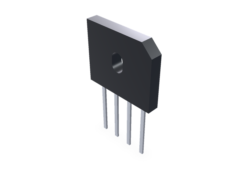
Single-phase bridge rectifiers in Vishay's through-hole cases: GBL, GBU, KBL and KBU in-line, KBPC1 and KBPC6 square, from Vishay's data sheets.
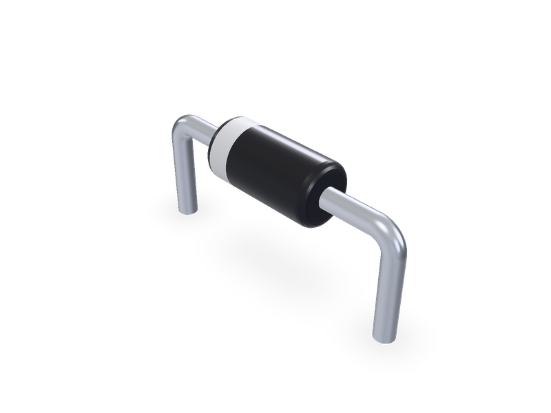
Axial leaded diodes in Vishay's DO-35, DO-41, DO-15, DO-201AD and P600 packages, with the cathode band, horizontal or vertical.
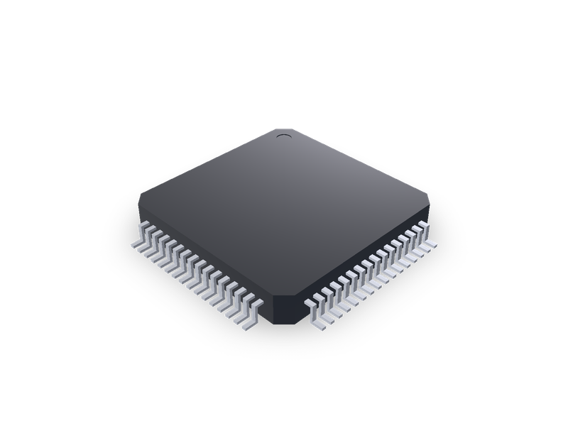
LQFP and TQFP packages with gull-wing leads on four sides, by TI package outline.