
STEVEMIT
steve/pin-socket
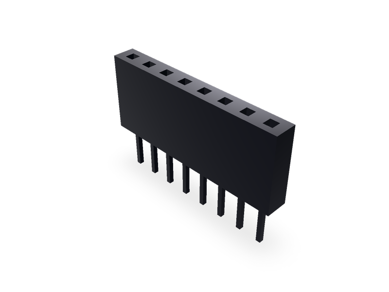
Pin socket (female header): 2.54 mm straight, 2.00 mm surface-mount, 1.27 mm surface-mount and right-angle, 1.00 mm straight and surface-mount, one or two rows.
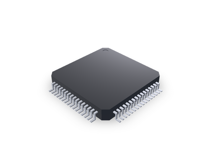
LQFP and TQFP packages with gull-wing leads on four sides, by TI package outline.
| 1 | """Quad flat package (LQFP, TQFP) with gull-wing leads on four sides, by TI package outline. Centred on the origin with the seating plane |
| 2 | on the XY plane. Seen from above, pin 1 is the top pin of the -X side and the pins count counter-clockwise: down the -X side, left to right |
| 3 | along the -Y side, up the +X side and right to left along the +Y side. Dimensions from the TI outline named by `package`; see the README.""" |
| 4 | from steve import Model |
| 5 | |
| 6 | package = "PM0064A" # TI package outline |
| 7 | detail = "full" # full: body, pin-1 mark and gull-wing leads; simple: the body only |
| 8 | |
| 9 | # outline: (kind, pins, pitch, body (min, max), lead tip to tip (min, max), height max, standoff (min, max), lead width (min, max), |
| 10 | # foot length (min, max)), in mm. Where an outline gives only the standoff's minimum (0.05 MIN), that value is used. |
| 11 | # TI package outlines, https://www.ti.com/lit/pdf/<doc>, page 1 "PACKAGE OUTLINE": |
| 12 | # VF0032A mtqf002 (4219769/A 04/2019), PT0048A mtqf003 (4215159/B 11/2023), PM0064A mtqf008 (4215162/A 03/2017), |
| 13 | # PN0080A mtqf010 (4215166/A 08/2022), PZ0100A mtqf013 (4215169/A 03/2017): LQFP, 1.6 mm max height; |
| 14 | # PFB0048A mtqf019 (4215157/A 03/2024), PFC0080A mtqf009 (4215165/B 06/2017): TQFP, 1.2 mm max height. |
| 15 | # Older "MECHANICAL DATA" sheets, comma decimals, which name the package by its letters (S-PQFP-G<pins>) and say "Falls within JEDEC |
| 16 | # MS-026": PGE (S-PQFP-G144) MTQF017A rev. December 1996 (4040147/C 10/96) and PBL (S-PQFP-G***, the 176-pin row) MTQF018C rev. May 1999 |
| 17 | # (4040154/C 06/96), 1,60 max, the LQFP height; PAG (S-PQFP-G64) MTQF006A rev. December 1996 (4040282/C 11/96) and PZT (S-PQFP-G100) |
| 18 | # MTQF012B rev. December 1996 (4073179/B 11/96), 1,20 max, the TQFP height. |
| 19 | OUTLINES = { |
| 20 | "VF0032A": ("LQFP", 32, 0.8, (6.8, 7.2), (8.8, 9.2), 1.6, (0.05, 0.15), (0.25, 0.45), (0.45, 0.75)), |
| 21 | "PT0048A": ("LQFP", 48, 0.5, (6.8, 7.2), (8.8, 9.2), 1.6, (0.05, 0.05), (0.17, 0.27), (0.45, 0.75)), |
| 22 | "PM0064A": ("LQFP", 64, 0.5, (9.8, 10.2), (11.8, 12.2), 1.6, (0.05, 0.05), (0.17, 0.27), (0.45, 0.75)), |
| 23 | "PN0080A": ("LQFP", 80, 0.5, (11.8, 12.2), (13.8, 14.2), 1.6, (0.05, 0.05), (0.17, 0.27), (0.45, 0.75)), |
| 24 | "PZ0100A": ("LQFP", 100, 0.5, (13.8, 14.2), (15.8, 16.2), 1.6, (0.05, 0.05), (0.17, 0.27), (0.45, 0.75)), |
| 25 | "PFB0048A": ("TQFP", 48, 0.5, (6.8, 7.2), (8.8, 9.2), 1.2, (0.05, 0.05), (0.17, 0.27), (0.45, 0.75)), |
| 26 | "PFC0080A": ("TQFP", 80, 0.5, (11.8, 12.2), (13.8, 14.2), 1.2, (0.05, 0.05), (0.17, 0.27), (0.45, 0.75)), |
| 27 | "PGE": ("LQFP", 144, 0.5, (19.8, 20.2), (21.8, 22.2), 1.6, (0.05, 0.05), (0.17, 0.27), (0.45, 0.75)), |
| 28 | "PBL": ("LQFP", 176, 0.4, (19.8, 20.2), (21.8, 22.2), 1.6, (0.05, 0.05), (0.13, 0.23), (0.45, 0.75)), |
| 29 | "PAG": ("TQFP", 64, 0.5, (9.8, 10.2), (11.8, 12.2), 1.2, (0.05, 0.05), (0.17, 0.27), (0.45, 0.75)), |
| 30 | "PZT": ("TQFP", 100, 0.5, (13.8, 14.2), (15.8, 16.2), 1.2, (0.05, 0.05), (0.17, 0.27), (0.45, 0.75)), |
| 31 | } |
| 32 | LEAD_T = 0.13 # lead thickness, the outlines' (0.13) TYP reference |
| 33 | # Proportions, for looks (drawn but not dimensioned): the body's corners are chamfered 0.06 x the body; the gull wing leaves the body at |
| 34 | # half its height; the pin-1 mark is a dimple of radius 0.04 x the body, 0.1 x the body in from the pin-1 corner. |
| 35 | CORNER = 0.06 |
| 36 | |
| 37 | if package not in OUTLINES: |
| 38 | raise ValueError(f"no outline {package!r}: {', '.join(OUTLINES)}") |
| 39 | |
| 40 | |
| 41 | def mid(pair): |
| 42 | return (pair[0] + pair[1]) / 2 |
| 43 | |
| 44 | |
| 45 | kind, pins, pitch, B, SPAN, top, STANDOFF, BW, FOOT = OUTLINES[package] |
| 46 | body, span, standoff, lead_w, foot = mid(B), mid(SPAN), mid(STANDOFF), mid(BW), mid(FOOT) |
| 47 | per_side = pins // 4 |
| 48 | first = (per_side - 1) * pitch / 2 |
| 49 | h = body / 2 |
| 50 | c = CORNER * body |
| 51 | model = Model() |
| 52 | model.plane("body_plane", on="XY", offset=standoff, name="Body") |
| 53 | with model.sketch("body_sketch", on="body_plane", name="Body") as sk: |
| 54 | sk.polyline("body_outline", [(-h + c, -h), (h - c, -h), (h, -h + c), (h, h - c), (h - c, h), (-h + c, h), (-h, h - c), (-h, -h + c)], |
| 55 | closed=True) |
| 56 | model.extrude("body", "body_sketch", distance=top - standoff, op="new", body="body_body", name="Body") |
| 57 | bodies = ["body_body"] |
| 58 | if detail == "full": |
| 59 | model.plane("top_plane", on="XY", offset=top, name="Top") |
| 60 | with model.sketch("mark_sketch", on="top_plane", name="Pin-1 mark") as sk: |
| 61 | sk.circle("mark_circle", (-h + 0.1 * body, h - 0.1 * body), 0.04 * body) |
| 62 | model.extrude("mark", "mark_sketch", distance=-0.05, op="cut", body="body_body", name="Pin-1 mark") |
| 63 | arm_z = (top + standoff) / 2 |
| 64 | out, bend = span / 2, span / 2 - foot |
| 65 | |
| 66 | T = LEAD_T |
| 67 | # One lead: the gull wing seen along its side (u out from the centre, z), extruded by the lead's width. The arm leaves the body at arm_z, |
| 68 | # the leg drops at the foot's inner end, and the foot runs out to the tip. All leads are in one leads body, one solid per lead. |
| 69 | wing = [(h, arm_z + T), (bend + T / 2, arm_z + T), (bend + T / 2, T), (out, T), (out, 0.0), (bend - T / 2, 0.0), (bend - T / 2, arm_z), |
| 70 | (h, arm_z)] |
| 71 | # Each side's first pin (YZ planes, normal +X, are sketched as (y, z); XZ planes, normal -Y, as (x, z)), repeated along the side in the |
| 72 | # counter-clockwise direction: -X side down from its top pin (pin 1), -Y side left to right, +X side upward, +Y side right to left. |
| 73 | row = first + lead_w / 2 |
| 74 | # (plane, the plane's x (YZ) or y (XZ), outward normal, step along the side) |
| 75 | sides = (("XZ", row, (-1, 0), (0, -1, 0)), ("YZ", -row, (0, -1), (1, 0, 0)), ("XZ", -row + lead_w, (1, 0), (0, 1, 0)), |
| 76 | ("YZ", row - lead_w, (0, 1), (-1, 0, 0))) |
| 77 | for k, (plane, at, (nx, ny), step) in enumerate(sides): |
| 78 | model.plane(f"lead_{k}_plane", on=plane, offset=at if plane == "YZ" else -at, name="Leads") |
| 79 | with model.sketch(f"lead_{k}_sketch", on=f"lead_{k}_plane", name="Leads") as sk: |
| 80 | sk.polyline(f"lead_{k}_wing", [((nx or ny) * u, z) for u, z in wing], closed=True) |
| 81 | # YZ planes extrude along +X and XZ planes along -Y, from the side's first pin. |
| 82 | start = f"lead_{k}" |
| 83 | model.extrude(start, f"lead_{k}_sketch", distance=lead_w, op="new" if k == 0 else "join", body="leads_body", name="Leads") |
| 84 | model.linear_pattern(f"lead_{k}_row", direction=step, count=per_side, spacing=pitch, features=[start], name="Leads") |
| 85 | bodies.append("leads_body") |
| 86 | # Materials, for looks and a rough mass: the moulding is epoxy compound, mostly silica filler (density about 1.9 to 2.0), and ptfe (2.2) is the |
| 87 | # nearest in the material list; the leads are tin-plated copper alloy, copper. |
| 88 | model.material("ptfe", bodies=["body_body"], color="#26282b") |
| 89 | if detail == "full": |
| 90 | model.material("copper", bodies=["leads_body"], color="#c9ccd1") |
| 91 | result = model.result() |
| 92 |
| 1 | name = "steve/qfp-package" |
| 2 | version = "1.0.0" |
| 3 | runtime = "steve" |
| 4 | license = "MIT" |
| 5 | summary = "LQFP and TQFP packages with gull-wing leads on four sides, by TI package outline." |
| 6 | description = """Quad flat package for board layouts, from TI's package outline drawings: LQFP (1.6 max) with 32, 48, 64, 80, 100, 144 and 176 pins and TQFP (1.2 max) with 48, 64, 80 and 100 pins, gull-wing leads on all four sides. Pin 1 at the top of the -X side, counting counter-clockwise. See the README.""" |
| 7 | tags = ["qfp", "lqfp", "tqfp", "ic", "package", "smd", "electronics"] |
| 8 | |
| 9 | [parameters.package] |
| 10 | type = "choice" |
| 11 | default = "PM0064A" |
| 12 | choices = ["VF0032A", "PT0048A", "PM0064A", "PN0080A", "PZ0100A", "PGE", "PBL", "PFB0048A", "PAG", "PFC0080A", "PZT"] |
| 13 | label = "TI package outline" |
| 14 | description = "LQFP: VF0032A (32, 7x7, 0.8), PT0048A (48, 7x7), PM0064A (64, 10x10), PN0080A (80, 12x12), PZ0100A (100, 14x14), PGE (144, 20x20), PBL (176, 20x20, 0.4). TQFP: PFB0048A (48, 7x7), PAG (64, 10x10), PFC0080A (80, 12x12), PZT (100, 14x14). Pitch 0.5 unless given." |
| 15 | |
| 16 | [parameters.detail] |
| 17 | type = "choice" |
| 18 | default = "full" |
| 19 | choices = ["full", "simple"] |
| 20 | label = "Detail" |
| 21 | description = "full: body, pin-1 mark and leads. simple: the body only, for big assemblies." |
| 22 | |
| 23 | [[presets]] |
| 24 | id = "LQFP-32-VF0032A" |
| 25 | title = "LQFP-32 (VF0032A), 7x7 mm body, 0.8 mm pitch" |
| 26 | params = { package = "VF0032A" } |
| 27 | aliases = ["LQFP-32 7x7mm P0.8mm", "LQFP32", "32 pin LQFP", "VF0032A"] |
| 28 | standard = "TI package outline" |
| 29 | |
| 30 | [[presets]] |
| 31 | id = "LQFP-48-PT0048A" |
| 32 | title = "LQFP-48 (PT0048A), 7x7 mm body, 0.5 mm pitch" |
| 33 | params = { package = "PT0048A" } |
| 34 | aliases = ["LQFP-48 7x7mm P0.5mm", "LQFP48", "48 pin LQFP", "PT0048A"] |
| 35 | standard = "TI package outline" |
| 36 | |
| 37 | [[presets]] |
| 38 | id = "LQFP-64-PM0064A" |
| 39 | title = "LQFP-64 (PM0064A), 10x10 mm body, 0.5 mm pitch" |
| 40 | params = { package = "PM0064A" } |
| 41 | aliases = ["LQFP-64 10x10mm P0.5mm", "LQFP64", "64 pin LQFP", "PM0064A"] |
| 42 | standard = "TI package outline" |
| 43 | |
| 44 | [[presets]] |
| 45 | id = "LQFP-80-PN0080A" |
| 46 | title = "LQFP-80 (PN0080A), 12x12 mm body, 0.5 mm pitch" |
| 47 | params = { package = "PN0080A" } |
| 48 | aliases = ["LQFP-80 12x12mm P0.5mm", "LQFP80", "80 pin LQFP", "PN0080A"] |
| 49 | standard = "TI package outline" |
| 50 | |
| 51 | [[presets]] |
| 52 | id = "LQFP-100-PZ0100A" |
| 53 | title = "LQFP-100 (PZ0100A), 14x14 mm body, 0.5 mm pitch" |
| 54 | params = { package = "PZ0100A" } |
| 55 | aliases = ["LQFP-100 14x14mm P0.5mm", "LQFP100", "100 pin LQFP", "PZ0100A"] |
| 56 | standard = "TI package outline" |
| 57 | |
| 58 | [[presets]] |
| 59 | id = "LQFP-144-PGE" |
| 60 | title = "LQFP-144 (PGE), 20x20 mm body, 0.5 mm pitch" |
| 61 | params = { package = "PGE" } |
| 62 | aliases = ["LQFP-144 20x20mm P0.5mm", "LQFP144", "144 pin LQFP", "PGE"] |
| 63 | standard = "TI package outline" |
| 64 | |
| 65 | [[presets]] |
| 66 | id = "LQFP-176-PBL" |
| 67 | title = "LQFP-176 (PBL), 20x20 mm body, 0.4 mm pitch" |
| 68 | params = { package = "PBL" } |
| 69 | aliases = ["LQFP-176 20x20mm P0.4mm", "LQFP176", "176 pin LQFP", "PBL"] |
| 70 | standard = "TI package outline" |
| 71 | |
| 72 | [[presets]] |
| 73 | id = "TQFP-48-PFB0048A" |
| 74 | title = "TQFP-48 (PFB0048A), 7x7 mm body, 0.5 mm pitch" |
| 75 | params = { package = "PFB0048A" } |
| 76 | aliases = ["TQFP-48 7x7mm P0.5mm", "TQFP48", "48 pin TQFP", "PFB0048A"] |
| 77 | standard = "TI package outline" |
| 78 | |
| 79 | [[presets]] |
| 80 | id = "TQFP-64-PAG" |
| 81 | title = "TQFP-64 (PAG), 10x10 mm body, 0.5 mm pitch" |
| 82 | params = { package = "PAG" } |
| 83 | aliases = ["TQFP-64 10x10mm P0.5mm", "TQFP64", "64 pin TQFP", "PAG"] |
| 84 | standard = "TI package outline" |
| 85 | |
| 86 | [[presets]] |
| 87 | id = "TQFP-80-PFC0080A" |
| 88 | title = "TQFP-80 (PFC0080A), 12x12 mm body, 0.5 mm pitch" |
| 89 | params = { package = "PFC0080A" } |
| 90 | aliases = ["TQFP-80 12x12mm P0.5mm", "TQFP80", "80 pin TQFP", "PFC0080A"] |
| 91 | standard = "TI package outline" |
| 92 | |
| 93 | [[presets]] |
| 94 | id = "TQFP-100-PZT" |
| 95 | title = "TQFP-100 (PZT), 14x14 mm body, 0.5 mm pitch" |
| 96 | params = { package = "PZT" } |
| 97 | aliases = ["TQFP-100 14x14mm P0.5mm", "TQFP100", "100 pin TQFP", "PZT"] |
| 98 | standard = "TI package outline" |
| 99 | |
| 100 | [[presets]] |
| 101 | id = "LQFP-64-PM0064A-simple" |
| 102 | title = "LQFP-64 (PM0064A), 10x10 mm body, 0.5 mm pitch, simple" |
| 103 | params = { package = "PM0064A", detail = "simple" } |
| 104 | aliases = ["LQFP-64 simple"] |
| 105 | standard = "TI package outline" |
| 106 |
A quad flat package (LQFP or TQFP) with gull-wing leads on all four sides, built from TI's package outline drawings. It is centred on the origin with the seating plane on the XY plane. Seen from above, pin 1 is the top pin of the -X side, and the pins count counter-clockwise: down the -X side, left to right along the -Y side, up the +X side and right to left along the +Y side. TI's older sheets (PGE, PBL, PAG, PZT) draw pin 1 at the left end of the bottom row. The order is the same counter-clockwise order, only the drawing is turned.
package |
Kind | Pins | Pitch | Body | Tip to tip | Height max | Lead width | Foot | Standoff |
|---|---|---|---|---|---|---|---|---|---|
| VF0032A | LQFP | 32 | 0.8 | 6.8–7.2 | 8.8–9.2 | 1.6 | 0.25–0.45 | 0.45–0.75 | 0.05–0.15 |
| PT0048A | LQFP | 48 | 0.5 | 6.8–7.2 | 8.8–9.2 | 1.6 | 0.17–0.27 | 0.45–0.75 | 0.05 min |
| PM0064A | LQFP | 64 | 0.5 | 9.8–10.2 | 11.8–12.2 | 1.6 | 0.17–0.27 | 0.45–0.75 | 0.05 min |
| PN0080A | LQFP | 80 | 0.5 | 11.8–12.2 | 13.8–14.2 | 1.6 | 0.17–0.27 | 0.45–0.75 | 0.05 min |
| PZ0100A | LQFP | 100 | 0.5 | 13.8–14.2 | 15.8–16.2 | 1.6 | 0.17–0.27 | 0.45–0.75 | 0.05 min |
| PGE | LQFP | 144 | 0.5 | 19.8–20.2 | 21.8–22.2 | 1.6 | 0.17–0.27 | 0.45–0.75 | 0.05 min |
| PBL | LQFP | 176 | 0.4 | 19.8–20.2 | 21.8–22.2 | 1.6 | 0.13–0.23 | 0.45–0.75 | 0.05 min |
| PFB0048A | TQFP | 48 | 0.5 | 6.8–7.2 | 8.8–9.2 | 1.2 | 0.17–0.27 | 0.45–0.75 | 0.05 min |
| PAG | TQFP | 64 | 0.5 | 9.8–10.2 | 11.8–12.2 | 1.2 | 0.17–0.27 | 0.45–0.75 | 0.05 min |
| PFC0080A | TQFP | 80 | 0.5 | 11.8–12.2 | 13.8–14.2 | 1.2 | 0.17–0.27 | 0.45–0.75 | 0.05 min |
| PZT | TQFP | 100 | 0.5 | 13.8–14.2 | 15.8–16.2 | 1.2 | 0.17–0.27 | 0.45–0.75 | 0.05 min |
The part uses the middle of each range. The body runs from the standoff up to the maximum height. Where an outline gives only the standoff's minimum, the part uses that value. The leads are 0.13 thick, the outlines' (0.13) typical value.
detail = "simple" leaves out the leads and the pin-1 mark.
TI package outline drawings, from ti.com (https://www.ti.com/lit/pdf/<document>), page 1, "PACKAGE OUTLINE":
Each drawing gives the body, the tip-to-tip span, the lead width, the foot length (0.45–0.75, measured from the gage plane), the standoff, the maximum height and the pitch.
Proportions, for looks only. The drawings show these but don't dimension them:
A catalogue name such as LQFP-64_10x10mm_P0.5mm gives the kind, the pin count, the body and the pitch, all from JEDEC MS-026. It maps to the TI outline of the same kind with the same pins, pitch and body, and 11 names map:
Measured on 15 reference models (LQFP-32, 44, 48, 64 at 0.5 and 0.8, 80, 100, 128, 144 and both 176s, and TQFP-48, 64, 80 and 100):
The other names in the family (other pin counts and bodies, exposed-pad and PQFP outlines, and the "Generic IC package families" entries, which give only a pin count) stay "no table read yet" until a TI outline of the same size is read.
| 1 | # QFP package |
| 2 | |
| 3 | A quad flat package (LQFP or TQFP) with gull-wing leads on all four sides, built from TI's package outline drawings. It is centred on the origin with the seating plane on the XY plane. Seen from above, pin 1 is the top pin of the -X side, and the pins count counter-clockwise: down the -X side, left to right along the -Y side, up the +X side and right to left along the +Y side. TI's older sheets (PGE, PBL, PAG, PZT) draw pin 1 at the left end of the bottom row. The order is the same counter-clockwise order, only the drawing is turned. |
| 4 | |
| 5 | | `package` | Kind | Pins | Pitch | Body | Tip to tip | Height max | Lead width | Foot | Standoff | |
| 6 | |---|---|---|---|---|---|---|---|---|---| |
| 7 | | VF0032A | LQFP | 32 | 0.8 | 6.8–7.2 | 8.8–9.2 | 1.6 | 0.25–0.45 | 0.45–0.75 | 0.05–0.15 | |
| 8 | | PT0048A | LQFP | 48 | 0.5 | 6.8–7.2 | 8.8–9.2 | 1.6 | 0.17–0.27 | 0.45–0.75 | 0.05 min | |
| 9 | | PM0064A | LQFP | 64 | 0.5 | 9.8–10.2 | 11.8–12.2 | 1.6 | 0.17–0.27 | 0.45–0.75 | 0.05 min | |
| 10 | | PN0080A | LQFP | 80 | 0.5 | 11.8–12.2 | 13.8–14.2 | 1.6 | 0.17–0.27 | 0.45–0.75 | 0.05 min | |
| 11 | | PZ0100A | LQFP | 100 | 0.5 | 13.8–14.2 | 15.8–16.2 | 1.6 | 0.17–0.27 | 0.45–0.75 | 0.05 min | |
| 12 | | PGE | LQFP | 144 | 0.5 | 19.8–20.2 | 21.8–22.2 | 1.6 | 0.17–0.27 | 0.45–0.75 | 0.05 min | |
| 13 | | PBL | LQFP | 176 | 0.4 | 19.8–20.2 | 21.8–22.2 | 1.6 | 0.13–0.23 | 0.45–0.75 | 0.05 min | |
| 14 | | PFB0048A | TQFP | 48 | 0.5 | 6.8–7.2 | 8.8–9.2 | 1.2 | 0.17–0.27 | 0.45–0.75 | 0.05 min | |
| 15 | | PAG | TQFP | 64 | 0.5 | 9.8–10.2 | 11.8–12.2 | 1.2 | 0.17–0.27 | 0.45–0.75 | 0.05 min | |
| 16 | | PFC0080A | TQFP | 80 | 0.5 | 11.8–12.2 | 13.8–14.2 | 1.2 | 0.17–0.27 | 0.45–0.75 | 0.05 min | |
| 17 | | PZT | TQFP | 100 | 0.5 | 13.8–14.2 | 15.8–16.2 | 1.2 | 0.17–0.27 | 0.45–0.75 | 0.05 min | |
| 18 | |
| 19 | The part uses the middle of each range. The body runs from the standoff up to the maximum height. Where an outline gives only the standoff's minimum, the part uses that value. The leads are 0.13 thick, the outlines' (0.13) typical value. |
| 20 | |
| 21 | `detail = "simple"` leaves out the leads and the pin-1 mark. |
| 22 | |
| 23 | ## Source |
| 24 | |
| 25 | TI package outline drawings, from ti.com (`https://www.ti.com/lit/pdf/<document>`), page 1, "PACKAGE OUTLINE": |
| 26 | |
| 27 | - LQFP, 1.6 mm max height: VF0032A, mtqf002 (4219769/A 04/2019); PT0048A, mtqf003 (4215159/B 11/2023); PM0064A, mtqf008 (4215162/A 03/2017); PN0080A, mtqf010 (4215166/A 08/2022); PZ0100A, mtqf013 (4215169/A 03/2017). Each refers to JEDEC registration MS-026. |
| 28 | - TQFP, 1.2 mm max height: PFB0048A, mtqf019 (4215157/A 03/2024); PFC0080A, mtqf009 (4215165/B 06/2017). |
| 29 | - TI's older "MECHANICAL DATA" sheets, with comma decimals, which name the package by its letters and say "Falls within JEDEC MS-026": |
| 30 | - PGE (S-PQFP-G144), MTQF017A revised December 1996 (4040147/C 10/96), 1,60 max: the LQFP height. |
| 31 | - PBL (S-PQFP-G***), MTQF018C revised May 1999 (4040154/C 06/96), the 176-pin row, 1,60 max. |
| 32 | - PAG (S-PQFP-G64), MTQF006A revised December 1996 (4040282/C 11/96), 1,20 max: the TQFP height. |
| 33 | - PZT (S-PQFP-G100), MTQF012B revised December 1996 (4073179/B 11/96), 1,20 max. |
| 34 | |
| 35 | Each drawing gives the body, the tip-to-tip span, the lead width, the foot length (0.45–0.75, measured from the gage plane), the standoff, the maximum height and the pitch. |
| 36 | |
| 37 | **Proportions, for looks only.** The drawings show these but don't dimension them: |
| 38 | |
| 39 | - The body's corners are chamfered by 0.06 x the body's side, and its sides have no draft. |
| 40 | - The gull wing leaves the body at half the body's height, drops at the foot's inner end, and runs out to the tip, with square bends. Each lead is one solid, its profile extruded by the lead's width. All the leads are in one body, so the part is two bodies: the moulding and the leads. |
| 41 | - The pin-1 mark is a dimple 0.05 deep, of radius 0.04 x the body, 0.1 x the body in from the pin-1 corner. |
| 42 | - Materials are for looks and a rough mass. The moulding is epoxy compound, mostly silica filler (density about 1.9 to 2.0), and ptfe (2.2) is the nearest in the material list. The leads are tin-plated copper alloy, so copper. |
| 43 | |
| 44 | ## Catalogue models |
| 45 | |
| 46 | A catalogue name such as `LQFP-64_10x10mm_P0.5mm` gives the kind, the pin count, the body and the pitch, all from JEDEC MS-026. It maps to the TI outline of the same kind with the same pins, pitch and body, and 11 names map: |
| 47 | |
| 48 | - LQFP-32 7x7 P0.8, LQFP-48 7x7 P0.5, LQFP-64 10x10 P0.5, LQFP-80 12x12 P0.5, LQFP-100 14x14 P0.5, LQFP-144 20x20 P0.5 and LQFP-176 20x20 P0.4. |
| 49 | - TQFP-48 7x7 P0.5, TQFP-64 10x10 P0.5, TQFP-80 12x12 P0.5 and TQFP-100 14x14 P0.5. |
| 50 | |
| 51 | Measured on 15 reference models (LQFP-32, 44, 48, 64 at 0.5 and 0.8, 80, 100, 128, 144 and both 176s, and TQFP-48, 64, 80 and 100): |
| 52 | |
| 53 | - Each one's tip-to-tip span is the nominal (body + 2, the middle of TI's range). |
| 54 | - The pins are at the named pitch, with lead widths of 0.35–0.40 at 0.8 pitch (TI 0.25–0.45), 0.22 at 0.5 (TI 0.17–0.27; 0.20 on the LQFP-80), and 0.18 at 0.4 (TI 0.13–0.23). |
| 55 | - The feet are 0.53 long on most LQFPs and 0.56 on the TQFP-64, 80 and 100, against TI's 0.45–0.75. The LQFP-48 and TQFP-48 models' feet are 0.44, 0.01 short of TI's minimum. |
| 56 | - The LQFP models are 1.5 high and the TQFP models 1.1, within TI's 1.6 and 1.2 maximums. |
| 57 | - The models' bodies are drafted, about 10.0 at the parting line for a 10 x 10 body, and the leads are 0.18 thick. |
| 58 | |
| 59 | The other names in the family (other pin counts and bodies, exposed-pad and PQFP outlines, and the "Generic IC package families" entries, which give only a pin count) stay "no table read yet" until a TI outline of the same size is read. |
| 60 |
Quad flat package for board layouts, from TI's package outline drawings: LQFP (1.6 max) with 32, 48, 64, 80, 100, 144 and 176 pins and TQFP (1.2 max) with 48, 64, 80 and 100 pins, gull-wing leads on all four sides. Pin 1 at the top of the -X side, counting counter-clockwise. See the README.
A quad flat package (LQFP or TQFP) with gull-wing leads on all four sides, built from TI's package outline drawings. It is centred on the origin with the seating plane on the XY plane. Seen from above, pin 1 is the top pin of the -X side, and the pins count counter-clockwise: down the -X side, left to right along the -Y side, up the +X side and right to left along the +Y side. TI's older sheets (PGE, PBL, PAG, PZT) draw pin 1 at the left end of the bottom row. The order is the same counter-clockwise order, only the drawing is turned.
package |
Kind | Pins | Pitch | Body | Tip to tip | Height max | Lead width | Foot | Standoff |
|---|---|---|---|---|---|---|---|---|---|
| VF0032A | LQFP | 32 | 0.8 | 6.8–7.2 | 8.8–9.2 | 1.6 | 0.25–0.45 | 0.45–0.75 | 0.05–0.15 |
| PT0048A | LQFP | 48 | 0.5 | 6.8–7.2 | 8.8–9.2 | 1.6 | 0.17–0.27 | 0.45–0.75 | 0.05 min |
| PM0064A | LQFP | 64 | 0.5 | 9.8–10.2 | 11.8–12.2 | 1.6 | 0.17–0.27 | 0.45–0.75 | 0.05 min |
| PN0080A | LQFP | 80 | 0.5 | 11.8–12.2 | 13.8–14.2 | 1.6 | 0.17–0.27 | 0.45–0.75 | 0.05 min |
| PZ0100A | LQFP | 100 | 0.5 | 13.8–14.2 | 15.8–16.2 | 1.6 | 0.17–0.27 | 0.45–0.75 | 0.05 min |
| PGE | LQFP | 144 | 0.5 | 19.8–20.2 | 21.8–22.2 | 1.6 | 0.17–0.27 | 0.45–0.75 | 0.05 min |
| PBL | LQFP | 176 | 0.4 | 19.8–20.2 | 21.8–22.2 | 1.6 | 0.13–0.23 | 0.45–0.75 | 0.05 min |
| PFB0048A | TQFP | 48 | 0.5 | 6.8–7.2 | 8.8–9.2 | 1.2 | 0.17–0.27 | 0.45–0.75 | 0.05 min |
| PAG | TQFP | 64 | 0.5 | 9.8–10.2 | 11.8–12.2 | 1.2 | 0.17–0.27 | 0.45–0.75 | 0.05 min |
| PFC0080A | TQFP | 80 | 0.5 | 11.8–12.2 | 13.8–14.2 | 1.2 | 0.17–0.27 | 0.45–0.75 | 0.05 min |
| PZT | TQFP | 100 | 0.5 | 13.8–14.2 | 15.8–16.2 | 1.2 | 0.17–0.27 | 0.45–0.75 | 0.05 min |
The part uses the middle of each range. The body runs from the standoff up to the maximum height. Where an outline gives only the standoff's minimum, the part uses that value. The leads are 0.13 thick, the outlines' (0.13) typical value.
detail = "simple" leaves out the leads and the pin-1 mark.
TI package outline drawings, from ti.com (https://www.ti.com/lit/pdf/<document>), page 1, "PACKAGE OUTLINE":
Each drawing gives the body, the tip-to-tip span, the lead width, the foot length (0.45–0.75, measured from the gage plane), the standoff, the maximum height and the pitch.
Proportions, for looks only. The drawings show these but don't dimension them:
A catalogue name such as LQFP-64_10x10mm_P0.5mm gives the kind, the pin count, the body and the pitch, all from JEDEC MS-026. It maps to the TI outline of the same kind with the same pins, pitch and body, and 11 names map:
Measured on 15 reference models (LQFP-32, 44, 48, 64 at 0.5 and 0.8, 80, 100, 128, 144 and both 176s, and TQFP-48, 64, 80 and 100):
The other names in the family (other pin counts and bodies, exposed-pad and PQFP outlines, and the "Generic IC package families" entries, which give only a pin count) stay "no table read yet" until a TI outline of the same size is read.
Pin socket (female header): 2.54 mm straight, 2.00 mm surface-mount, 1.27 mm surface-mount and right-angle, 1.00 mm straight and surface-mount, one or two rows.
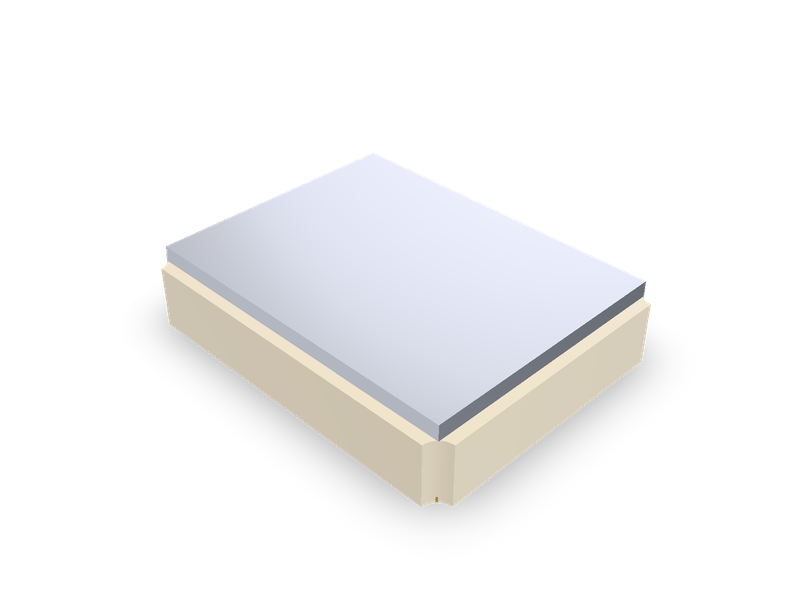
SMD quartz crystals by maker series: Epson FA-238, FA-238V, TSX-3225, MA-406, MA-505; TXC 7M, AX; Abracon ABM8G, ABM3B; EuroQuartz MT.
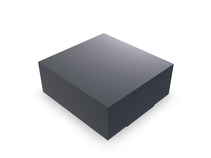
Molded SMD power inductors in the Sunlord MWSA-S sizes, 4.2 x 4.4 mm to 22 x 23.5 mm, by the maker's dimension table.
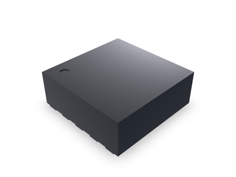
No-lead small-outline IC packages by TI outline: WSON-8/10/12/16, VSON-8 and X1SON-8, 0.4 to 0.8 mm pitch, with exposed thermal pad.