
STEVEMIT
steve/melf-resistor
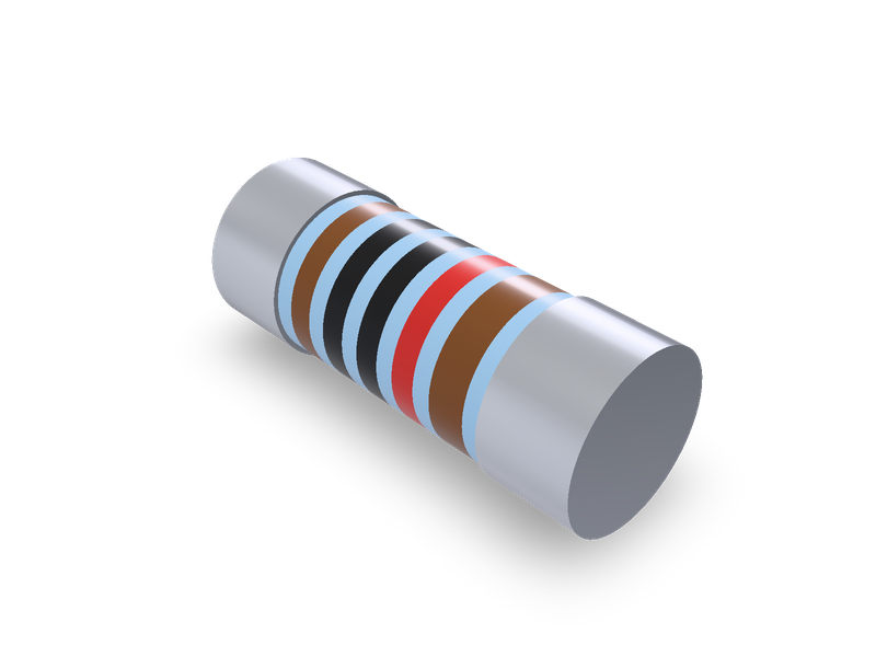
Thin film MELF resistors, Vishay Beyschlag MMU 0102 (MicroMELF), MMA 0204 (MiniMELF) and MMB 0207 (MELF), with colour rings.
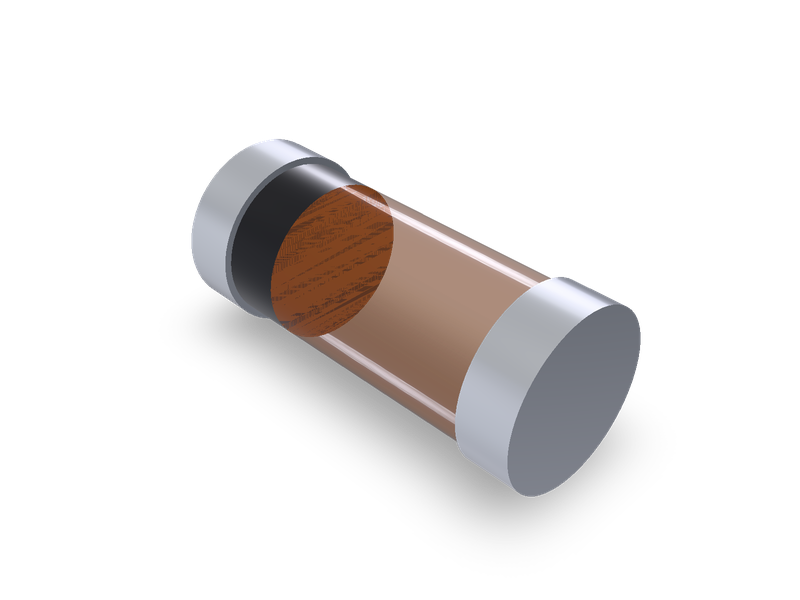
Surface-mount diode packages MELF (DO-213AB), MiniMELF (SOD-80) and MicroMELF, from Vishay's package drawings.
| 1 | """Surface-mount diode in a MELF package (MELF DO-213AB, MiniMELF SOD-80 or MicroMELF), by Vishay's package drawings. Lying on the XY plane |
| 2 | (the board) with its axis along X and centred on the origin in X and Y: the body between two metal end caps, and the cathode band on the body |
| 3 | at the -X end. Each end cap is its own solid. Dimensions from Vishay's drawings; see the README.""" |
| 4 | from steve import Model |
| 5 | |
| 6 | package = "MiniMELF" # MELF (DO-213AB, plastic), MiniMELF (SOD-80) or MicroMELF |
| 7 | |
| 8 | # package: (other name, body section, length, end cap diameter, end cap length, body across, body across the corners), ranges (min, max) in |
| 9 | # mm; None where the drawing doesn't give it. |
| 10 | # Vishay Semiconductors, "Package Dimensions for ESD-, Zener-, Small Signal Switching-, and Schottky Diodes", document number 80128, |
| 11 | # revision 1.4, 11-Oct-2022 (https://www.vishay.com/docs/80128/package_information.pdf), "PACKAGE DIMENSIONS in millimeters (inches)": |
| 12 | # MELF DO-213AB (PLASTIC) page 33 (drawing S8-V-3453.03-001, 13 May 2009): body D1 2.41 to 2.67, end caps D2 = D1 + 0 to 0.2 (here |
| 13 | # 2.41 to 2.87, whose middle is D1's middle + 0.1), end caps 0.46 to 0.56 long, 4.7 to 5.2 long; |
| 14 | # MiniMELF (SOD-80) page 37 (drawing 6.560-5005.01-4, rev. 8, 07 Jun 2006): end caps 1.4 to 1.6 across and 0.47 max. long (the only |
| 15 | # value given, used as is), 3.3 to 3.7 long; |
| 16 | # MicroMELF page 35 (drawing 6.560-5007.01-4, rev. 13, 07 Jun 2006): end caps 1.1 to 1.2 across and 0.15 to 0.25 long, 1.8 to 2.0 long; |
| 17 | # the glass is a rounded square, 0.6 from the axis to its flat ("surface plan") sides, so 1.2 across them, and under 1.35 across the |
| 18 | # corners (1.35 used). |
| 19 | OUTLINES = { |
| 20 | "MELF": ("DO-213AB", "round", (4.7, 5.2), (2.41, 2.87), (0.46, 0.56), (2.41, 2.67), None), |
| 21 | "MiniMELF": ("SOD-80", "round", (3.3, 3.7), (1.4, 1.6), (0.47, 0.47), None, None), |
| 22 | "MicroMELF": ("", "square", (1.8, 2.0), (1.1, 1.2), (0.15, 0.25), (1.2, 1.2), (1.35, 1.35)), |
| 23 | } |
| 24 | # Proportions, for looks (the drawings show these but don't dimension them): the glass body of the MiniMELF is GLASS of its end caps' |
| 25 | # diameter; the cathode band runs from the -X end cap BAND of the way along the body. |
| 26 | GLASS = 0.92 |
| 27 | BAND = 0.2 |
| 28 | |
| 29 | |
| 30 | def mid(pair): |
| 31 | return (pair[0] + pair[1]) / 2 |
| 32 | |
| 33 | |
| 34 | other, section, LEN, CAP_D, CAP_L, ACROSS, CORNERS = OUTLINES[package] |
| 35 | length, cap_d, cap_l = mid(LEN), mid(CAP_D), mid(CAP_L) |
| 36 | across = mid(ACROSS) if ACROSS else GLASS * cap_d |
| 37 | # The part rests on whichever is lower: the end caps or the body (MicroMELF's flat glass sides). |
| 38 | axis_z = max(cap_d, across) / 2 |
| 39 | inside = length / 2 - cap_l |
| 40 | band = BAND * 2 * inside |
| 41 | model = Model() |
| 42 | # Each cylinder starts at `at` and runs along +X. |
| 43 | for tag, side in (("cathode", -1), ("anode", 1)): |
| 44 | model.cylinder(f"{tag}_cap", cap_d / 2, cap_l, at=(-length / 2 if side < 0 else inside, 0, axis_z), direction=(1, 0, 0), op="new", |
| 45 | body=f"{tag}_cap_body", name="End caps") |
| 46 | if section == "round": |
| 47 | model.cylinder("band", across / 2, band, at=(-inside, 0, axis_z), direction=(1, 0, 0), op="new", body="band_body", |
| 48 | name="Cathode band") |
| 49 | model.cylinder("body", across / 2, 2 * inside - band, at=(-inside + band, 0, axis_z), direction=(1, 0, 0), op="new", body="body_body", |
| 50 | name="Body") |
| 51 | else: |
| 52 | # A square across the flats with its corners rounded to the given size across the corners: the corner radius r makes the diagonal |
| 53 | # 2 * (h * sqrt(2) - r * (sqrt(2) - 1)) for half-width h. |
| 54 | h = across / 2 |
| 55 | r = (h * 2 ** 0.5 - mid(CORNERS) / 2) / (2 ** 0.5 - 1) |
| 56 | for tag, x0, x1 in (("band", -inside, -inside + band), ("body", -inside + band, inside)): |
| 57 | model.plane(f"{tag}_plane", on="YZ", offset=x0, name="Body") |
| 58 | with model.sketch(f"{tag}_sketch", on=f"{tag}_plane", name="Body") as sk: |
| 59 | for i, (sy, sz) in enumerate(((1, 1), (-1, 1), (-1, -1), (1, -1))): |
| 60 | sk.arc(f"{tag}_corner_{i}", (sy * (h - r), axis_z + sz * (h - r)), r, 90 * i, 90 * i + 90) |
| 61 | sk.line(f"{tag}_top", (h - r, axis_z + h), (-h + r, axis_z + h)) |
| 62 | sk.line(f"{tag}_left", (-h, axis_z + h - r), (-h, axis_z - h + r)) |
| 63 | sk.line(f"{tag}_bottom", (-h + r, axis_z - h), (h - r, axis_z - h)) |
| 64 | sk.line(f"{tag}_right", (h, axis_z - h + r), (h, axis_z + h - r)) |
| 65 | model.extrude(tag, f"{tag}_sketch", distance=x1 - x0, op="new", body=f"{tag}_body", name="Cathode band" if tag == "band" else "Body") |
| 66 | # Materials, for looks and a rough mass. MELF's body is moulded epoxy over a glass body (Vishay GL41 data sheet), ptfe (2.07) the nearest |
| 67 | # to a silica-filled epoxy (about 1.9 to 2.0) in the material list; MiniMELF's and MicroMELF's bodies are glass, soda-lime glass; the end |
| 68 | # caps are plated metal, copper; the band is marking ink, shown in ptfe. |
| 69 | if package == "MELF": |
| 70 | model.material("ptfe", bodies=["body_body"], color="#2b2d30") |
| 71 | model.material("ptfe", bodies=["band_body"], color="#c8c8c4") |
| 72 | else: |
| 73 | model.material("glass-soda-lime", bodies=["body_body"], color="#c0602a") |
| 74 | model.material("ptfe", bodies=["band_body"], color="#1d1d1f") |
| 75 | model.material("copper", bodies=["cathode_cap_body", "anode_cap_body"], color="#c9ccd1") |
| 76 | result = model.result() |
| 77 |
| 1 | name = "steve/melf-diode" |
| 2 | version = "1.0.0" |
| 3 | runtime = "steve" |
| 4 | license = "MIT" |
| 5 | summary = "Surface-mount diode packages MELF (DO-213AB), MiniMELF (SOD-80) and MicroMELF, from Vishay's package drawings." |
| 6 | description = """Cylindrical surface-mount diode packages for board layouts and enclosures: the body between two metal end caps, each end cap its own solid, and the cathode band. MELF (DO-213AB) is the plastic package; MiniMELF (SOD-80) and MicroMELF are glass. Dimensions from Vishay's package drawings (document 80128). See the README.""" |
| 7 | tags = ["diode", "smd", "melf", "minimelf", "micromelf", "do-213ab", "sod-80", "electronics"] |
| 8 | |
| 9 | [parameters.package] |
| 10 | type = "choice" |
| 11 | default = "MiniMELF" |
| 12 | choices = ["MELF", "MiniMELF", "MicroMELF"] |
| 13 | label = "Package" |
| 14 | description = "MELF: DO-213AB, plastic. MiniMELF: SOD-80, glass. MicroMELF: glass." |
| 15 | |
| 16 | [[presets]] |
| 17 | id = "MELF" |
| 18 | title = "MELF (DO-213AB) diode package, Vishay drawing" |
| 19 | params = { package = "MELF" } |
| 20 | aliases = ["DO-213AB", "MELF diode", "DO-213AB diode"] |
| 21 | standard = "Vishay 80128" |
| 22 | |
| 23 | [[presets]] |
| 24 | id = "MiniMELF" |
| 25 | title = "MiniMELF (SOD-80) diode package, Vishay drawing" |
| 26 | params = { package = "MiniMELF" } |
| 27 | aliases = ["SOD-80", "MiniMELF diode", "SOD-80 diode"] |
| 28 | standard = "Vishay 80128" |
| 29 | |
| 30 | [[presets]] |
| 31 | id = "MicroMELF" |
| 32 | title = "MicroMELF diode package, Vishay drawing" |
| 33 | params = { package = "MicroMELF" } |
| 34 | aliases = ["MicroMELF diode"] |
| 35 | standard = "Vishay 80128" |
| 36 |
Cylindrical surface-mount diode packages: MELF (DO-213AB, plastic), MiniMELF (SOD-80, glass) and MicroMELF (glass), as Vishay draws them. The package lies on the XY plane (the board) with its axis along X, centred on the origin in X and Y. It is the body between two metal end caps, with the cathode band on the body at the -X end. Each end cap is its own solid.
Vishay Semiconductors, "Package Dimensions for ESD-, Zener-, Small Signal Switching-, and Schottky Diodes", document number 80128, revision 1.4, 11-Oct-2022, https://www.vishay.com/docs/80128/package_information.pdf. Each page is "PACKAGE DIMENSIONS in millimeters (inches)":
| Package | Length | End cap diameter | End cap length | Body |
|---|---|---|---|---|
| MELF | 4.7–5.2 | D2 = D1 + 0 to 0.2 | 0.46–0.56 | D1 = 2.41–2.67 |
| MiniMELF | 3.3–3.7 | 1.4–1.6 | 0.47 max. | not given |
| MicroMELF | 1.8–2.0 | 1.1–1.2 | 0.15–0.25 | glass: 0.6 from the axis to its flat sides; under 1.35 across the corners |
The model uses the middle of each range. MELF's end caps are 0.1 larger than its body, the middle of D1 + 0 to 0.2. MiniMELF's end cap length is given only as 0.47 max., so 0.47 is used. MicroMELF's glass is a square 1.2 across its flat sides with its corners rounded to 1.35 across, the limit given; the drawing's sides bulge slightly (radius over 2.5), and they are modelled flat. MicroMELF rests on its glass's flat side, the others on their end caps.
Proportions, stated plainly. The drawings show these but don't dimension them:
Materials and mass. MELF's body is moulded epoxy over a glass body (Vishay's GL41 data sheet). It is ptfe (2.07), the nearest in the material list to a silica-filled epoxy (about 1.9 to 2.0). MiniMELF's and MicroMELF's bodies are glass, soda-lime glass. The end caps are plated metal, shown as copper. The band is marking ink, shown in ptfe. Vishay's data sheets give each package's weight:
| Package | Model | Vishay's weight | Data sheet |
|---|---|---|---|
| MELF | 91 mg | 0.114 g | GL41, document 88546, revision 18-May-2021 (vishay.com) |
| MiniMELF | 25 mg | approx. 31 mg | LL4148-M, document 81162, rev. 1.4, 25-Jun-2024 (vishay.com) |
| MicroMELF | 9 mg | approx. 12 mg | MCL4151, document 85567, rev. 2.2, 25-Jun-2024 (vishay.com) |
The models come out lighter than stated, because the metal slugs and the die inside the body aren't modelled.
The old catalogue's D_MELF, D_MiniMELF and D_MicroMELF entries have no models to measure. Each names its package, and each maps to Vishay's drawing of that package. MELF is DO-213AB, and its plastic drawing is used, which is the one that dimensions the body. Vishay also draws a glass DO-213AB, 2.4 to 2.6 across, which isn't offered.
The family is shared with do214-diode (SMA, SMB and SMC). The other surface-mount diode packages in it aren't read here; see COVERAGE.md.
| 1 | # MELF diode package |
| 2 | |
| 3 | Cylindrical surface-mount diode packages: MELF (DO-213AB, plastic), MiniMELF (SOD-80, glass) and MicroMELF (glass), as Vishay draws them. The package lies on the XY plane (the board) with its axis along X, centred on the origin in X and Y. It is the body between two metal end caps, with the cathode band on the body at the -X end. Each end cap is its own solid. |
| 4 | |
| 5 | ## Source |
| 6 | |
| 7 | Vishay Semiconductors, "Package Dimensions for ESD-, Zener-, Small Signal Switching-, and Schottky Diodes", document number 80128, revision 1.4, 11-Oct-2022, <https://www.vishay.com/docs/80128/package_information.pdf>. Each page is "PACKAGE DIMENSIONS in millimeters (inches)": |
| 8 | |
| 9 | - MELF DO-213AB (PLASTIC): page 33, drawing S8-V-3453.03-001, 13 May 2009. The same drawing is in Vishay's GL41 data sheet, document 88546, revision 18-May-2021. |
| 10 | - MiniMELF (SOD-80): page 37, drawing 6.560-5005.01-4, rev. 8, 07 Jun 2006. |
| 11 | - MicroMELF: page 35, drawing 6.560-5007.01-4, rev. 13, 07 Jun 2006. |
| 12 | |
| 13 | | Package | Length | End cap diameter | End cap length | Body | |
| 14 | |---|---|---|---|---| |
| 15 | | MELF | 4.7–5.2 | D2 = D1 + 0 to 0.2 | 0.46–0.56 | D1 = 2.41–2.67 | |
| 16 | | MiniMELF | 3.3–3.7 | 1.4–1.6 | 0.47 max. | not given | |
| 17 | | MicroMELF | 1.8–2.0 | 1.1–1.2 | 0.15–0.25 | glass: 0.6 from the axis to its flat sides; under 1.35 across the corners | |
| 18 | |
| 19 | The model uses the middle of each range. MELF's end caps are 0.1 larger than its body, the middle of D1 + 0 to 0.2. MiniMELF's end cap length is given only as 0.47 max., so 0.47 is used. MicroMELF's glass is a square 1.2 across its flat sides with its corners rounded to 1.35 across, the limit given; the drawing's sides bulge slightly (radius over 2.5), and they are modelled flat. MicroMELF rests on its glass's flat side, the others on their end caps. |
| 20 | |
| 21 | **Proportions, stated plainly.** The drawings show these but don't dimension them: |
| 22 | |
| 23 | - MiniMELF's glass body is 0.92 of its end caps' diameter. The drawing shows it a little smaller than the caps. |
| 24 | - The cathode band is flush with the body. It runs from the -X end cap 0.2 of the way along the body. The drawings place it near that end cap but don't dimension it. |
| 25 | - The body runs from end cap to end cap. The small gap the glass drawings show at one end isn't modelled. |
| 26 | |
| 27 | **Materials and mass.** MELF's body is moulded epoxy over a glass body (Vishay's GL41 data sheet). It is ptfe (2.07), the nearest in the material list to a silica-filled epoxy (about 1.9 to 2.0). MiniMELF's and MicroMELF's bodies are glass, soda-lime glass. The end caps are plated metal, shown as copper. The band is marking ink, shown in ptfe. Vishay's data sheets give each package's weight: |
| 28 | |
| 29 | | Package | Model | Vishay's weight | Data sheet | |
| 30 | |---|---|---|---| |
| 31 | | MELF | 91 mg | 0.114 g | GL41, document 88546, revision 18-May-2021 (vishay.com) | |
| 32 | | MiniMELF | 25 mg | approx. 31 mg | LL4148-M, document 81162, rev. 1.4, 25-Jun-2024 (vishay.com) | |
| 33 | | MicroMELF | 9 mg | approx. 12 mg | MCL4151, document 85567, rev. 2.2, 25-Jun-2024 (vishay.com) | |
| 34 | |
| 35 | The models come out lighter than stated, because the metal slugs and the die inside the body aren't modelled. |
| 36 | |
| 37 | ## Catalogue models |
| 38 | |
| 39 | The old catalogue's `D_MELF`, `D_MiniMELF` and `D_MicroMELF` entries have no models to measure. Each names its package, and each maps to Vishay's drawing of that package. MELF is DO-213AB, and its plastic drawing is used, which is the one that dimensions the body. Vishay also draws a glass DO-213AB, 2.4 to 2.6 across, which isn't offered. |
| 40 | |
| 41 | The family is shared with `do214-diode` (SMA, SMB and SMC). The other surface-mount diode packages in it aren't read here; see `COVERAGE.md`. |
| 42 |
Cylindrical surface-mount diode packages for board layouts and enclosures: the body between two metal end caps, each end cap its own solid, and the cathode band. MELF (DO-213AB) is the plastic package; MiniMELF (SOD-80) and MicroMELF are glass. Dimensions from Vishay's package drawings (document 80128). See the README.
Cylindrical surface-mount diode packages: MELF (DO-213AB, plastic), MiniMELF (SOD-80, glass) and MicroMELF (glass), as Vishay draws them. The package lies on the XY plane (the board) with its axis along X, centred on the origin in X and Y. It is the body between two metal end caps, with the cathode band on the body at the -X end. Each end cap is its own solid.
Vishay Semiconductors, "Package Dimensions for ESD-, Zener-, Small Signal Switching-, and Schottky Diodes", document number 80128, revision 1.4, 11-Oct-2022, https://www.vishay.com/docs/80128/package_information.pdf. Each page is "PACKAGE DIMENSIONS in millimeters (inches)":
| Package | Length | End cap diameter | End cap length | Body |
|---|---|---|---|---|
| MELF | 4.7–5.2 | D2 = D1 + 0 to 0.2 | 0.46–0.56 | D1 = 2.41–2.67 |
| MiniMELF | 3.3–3.7 | 1.4–1.6 | 0.47 max. | not given |
| MicroMELF | 1.8–2.0 | 1.1–1.2 | 0.15–0.25 | glass: 0.6 from the axis to its flat sides; under 1.35 across the corners |
The model uses the middle of each range. MELF's end caps are 0.1 larger than its body, the middle of D1 + 0 to 0.2. MiniMELF's end cap length is given only as 0.47 max., so 0.47 is used. MicroMELF's glass is a square 1.2 across its flat sides with its corners rounded to 1.35 across, the limit given; the drawing's sides bulge slightly (radius over 2.5), and they are modelled flat. MicroMELF rests on its glass's flat side, the others on their end caps.
Proportions, stated plainly. The drawings show these but don't dimension them:
Materials and mass. MELF's body is moulded epoxy over a glass body (Vishay's GL41 data sheet). It is ptfe (2.07), the nearest in the material list to a silica-filled epoxy (about 1.9 to 2.0). MiniMELF's and MicroMELF's bodies are glass, soda-lime glass. The end caps are plated metal, shown as copper. The band is marking ink, shown in ptfe. Vishay's data sheets give each package's weight:
| Package | Model | Vishay's weight | Data sheet |
|---|---|---|---|
| MELF | 91 mg | 0.114 g | GL41, document 88546, revision 18-May-2021 (vishay.com) |
| MiniMELF | 25 mg | approx. 31 mg | LL4148-M, document 81162, rev. 1.4, 25-Jun-2024 (vishay.com) |
| MicroMELF | 9 mg | approx. 12 mg | MCL4151, document 85567, rev. 2.2, 25-Jun-2024 (vishay.com) |
The models come out lighter than stated, because the metal slugs and the die inside the body aren't modelled.
The old catalogue's D_MELF, D_MiniMELF and D_MicroMELF entries have no models to measure. Each names its package, and each maps to Vishay's drawing of that package. MELF is DO-213AB, and its plastic drawing is used, which is the one that dimensions the body. Vishay also draws a glass DO-213AB, 2.4 to 2.6 across, which isn't offered.
The family is shared with do214-diode (SMA, SMB and SMC). The other surface-mount diode packages in it aren't read here; see COVERAGE.md.
Thin film MELF resistors, Vishay Beyschlag MMU 0102 (MicroMELF), MMA 0204 (MiniMELF) and MMB 0207 (MELF), with colour rings.
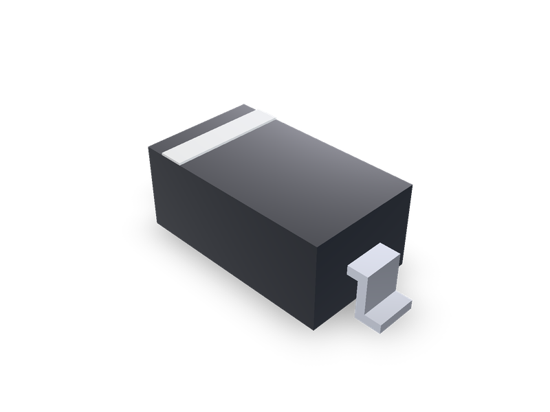
Surface-mount diode packages SOD-123, SOD-323, SOD-523 and SMF (DO-219AB), from Vishay's package drawings.
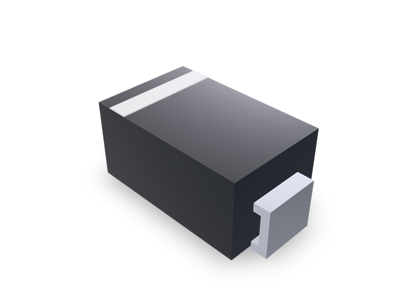
Surface-mount diode packages DO-214AC (SMA), DO-214AA (SMB) and DO-214AB (SMC), from Vishay's outline drawings.
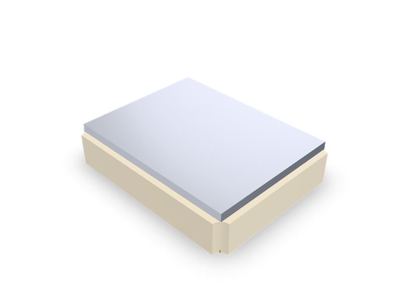
SMD quartz crystals by maker series: Epson FA-238, FA-238V, TSX-3225, MA-406, MA-505; TXC 7M, AX; Abracon ABM8G, ABM3B; EuroQuartz MT.