
STEVEMIT
steve/t-slot-extrusion
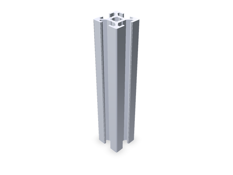
T-slot aluminium extrusions with real cross-sections (2020, 2040, 3030, 3060, 4040, 4080; slot 5, 6, 8), any length.
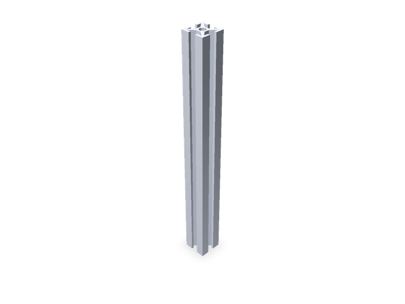
MakerBeam 10 x 10 mm aluminium profile, any length, from MakerBeam's own drawing.
| 1 | """MakerBeam 10 x 10 aluminium profile (MakerBeam article 100168 drawing), any length. |
| 2 | |
| 3 | The section, centred on the origin in the XY plane, extruded along +Z by `length`: a 10 x 10 square with a 3 mm slot |
| 4 | in each face (lip 1 thick), the slot widening under the lips into a dovetail whose walls run at 41.1 degrees down to |
| 5 | the 4 x 4 core, and a 2.5 mm centre bore (the tap drill of the M3 end threads; the threads are not modelled). All |
| 6 | four sides are the same, turned 90 degrees. MakerBeam's 0.2 mm corner and edge radii are not modelled. |
| 7 | """ |
| 8 | import math |
| 9 | |
| 10 | from steve import Model |
| 11 | |
| 12 | length = 100 # mm Length |
| 13 | finish = "clear" # Anodising |
| 14 | |
| 15 | # mm, from MakerBeam's drawing of article 100168 (beam clear anodised, M3, Ø2.5): DXF geometry and printed dimensions |
| 16 | SECTION = { |
| 17 | "outer": 10.0, # □10 |
| 18 | "slot": 3.0, # slot opening |
| 19 | "lip": 1.0, # lip thickness (face to lip underside) |
| 20 | "core": 4.0, # □4 core (slot floor 2.0 from the centre) |
| 21 | "bore": 2.5, # Ø2.5 centre bore |
| 22 | # the undercut wall, a straight line in the DXF (x, y from the centre, top slot): two points on it |
| 23 | "wall": ((2.8908, 3.6493), (1.0565, 2.0493)), |
| 24 | } |
| 25 | FINISHES = {"clear": "#cfd2d6", "black": "#2b2c2e"} |
| 26 | |
| 27 | half, s2 = SECTION["outer"] / 2, SECTION["slot"] / 2 |
| 28 | lip_y, floor_y = half - SECTION["lip"], SECTION["core"] / 2 |
| 29 | (x1, y1), (x2, y2) = SECTION["wall"] |
| 30 | slope = (y1 - y2) / (x1 - x2) |
| 31 | under = x1 + (lip_y - y1) / slope # where the wall meets the lip underside |
| 32 | foot = x2 + (floor_y - y2) / slope # where the wall meets the slot floor |
| 33 | top = [(-half, half), (-s2, half), (-s2, lip_y), (-under, lip_y), (-foot, floor_y), (foot, floor_y), |
| 34 | (under, lip_y), (s2, lip_y), (s2, half)] |
| 35 | outline = [] |
| 36 | for quarter in range(4): # top, right, bottom, left: each side is the top one turned 90 degrees clockwise |
| 37 | a = -math.pi / 2 * quarter |
| 38 | outline += [(x * math.cos(a) - y * math.sin(a), x * math.sin(a) + y * math.cos(a)) for x, y in top] |
| 39 | |
| 40 | model = Model() |
| 41 | with model.sketch("section", on="XY", name="Section") as sk: |
| 42 | sk.polyline("outline", outline) |
| 43 | sk.circle("bore", (0, 0), SECTION["bore"] / 2) |
| 44 | model.extrude("beam", "section", distance=length, name="Beam") |
| 45 | model.material("aluminum-generic", color=FINISHES[finish]) # 6063-T5 (no STEVE entry for 6063) |
| 46 | result = model.result() |
| 47 |
| 1 | name = "steve/makerbeam-profile" |
| 2 | version = "1.0.0" |
| 3 | runtime = "steve" |
| 4 | license = "MIT" |
| 5 | summary = "MakerBeam 10 x 10 mm aluminium profile, any length, from MakerBeam's own drawing." |
| 6 | description = """The MakerBeam 10 x 10 mm aluminium beam: a 3 mm slot on each face over a dovetail undercut, a 4 x 4 core \ |
| 7 | and a 2.5 mm centre bore (M3 end threads, not modelled), extruded to any length. Section from MakerBeam's drawing of \ |
| 8 | article 100168 (DXF geometry and printed dimensions); the 0.2 mm radii are not modelled. |
| 9 | |
| 10 | Centred on the origin in the XY plane, extruded along +Z. Dimensions: see the README.""" |
| 11 | tags = ["profile", "extrusion", "aluminium", "makerbeam", "10x10", "t-slot", "metric"] |
| 12 | |
| 13 | [parameters.length] |
| 14 | type = "number" |
| 15 | default = 100 |
| 16 | min = 5 |
| 17 | max = 3000 |
| 18 | unit = "mm" |
| 19 | label = "Length" |
| 20 | |
| 21 | [parameters.finish] |
| 22 | type = "choice" |
| 23 | default = "clear" |
| 24 | choices = ["clear", "black"] |
| 25 | label = "Anodising" |
| 26 | |
| 27 | [[presets]] |
| 28 | id = "MB10x10-40" |
| 29 | title = "MakerBeam 10 × 10, 40 mm" |
| 30 | params = { length = 40 } |
| 31 | aliases = ["MakerBeam 40 mm", "MakerBeam 10x10x40", "1010 profile 40 mm", "1010 extrusion 40 mm", "10 x 10 extrusion 40 mm"] |
| 32 | standard = "MakerBeam 100168" |
| 33 | |
| 34 | [[presets]] |
| 35 | id = "MB10x10-60" |
| 36 | title = "MakerBeam 10 × 10, 60 mm" |
| 37 | params = { length = 60 } |
| 38 | aliases = ["MakerBeam 60 mm", "MakerBeam 10x10x60", "1010 profile 60 mm", "1010 extrusion 60 mm", "10 x 10 extrusion 60 mm", "MakerBeam 10 × 10, 60 mm"] |
| 39 | standard = "MakerBeam 100168" |
| 40 | |
| 41 | [[presets]] |
| 42 | id = "MB10x10-100" |
| 43 | title = "MakerBeam 10 × 10, 100 mm" |
| 44 | params = { length = 100 } |
| 45 | aliases = ["MakerBeam 100 mm", "MakerBeam 10x10x100", "1010 profile 100 mm", "1010 extrusion 100 mm", "10 x 10 extrusion 100 mm", "MakerBeam 10 × 10, 100 mm"] |
| 46 | standard = "MakerBeam 100168" |
| 47 | |
| 48 | [[presets]] |
| 49 | id = "MB10x10-150" |
| 50 | title = "MakerBeam 10 × 10, 150 mm" |
| 51 | params = { length = 150 } |
| 52 | aliases = ["MakerBeam 150 mm", "MakerBeam 10x10x150", "1010 profile 150 mm", "1010 extrusion 150 mm", "10 x 10 extrusion 150 mm"] |
| 53 | standard = "MakerBeam 100168" |
| 54 | |
| 55 | [[presets]] |
| 56 | id = "MB10x10-200" |
| 57 | title = "MakerBeam 10 × 10, 200 mm" |
| 58 | params = { length = 200 } |
| 59 | aliases = ["MakerBeam 200 mm", "MakerBeam 10x10x200", "1010 profile 200 mm", "1010 extrusion 200 mm", "10 x 10 extrusion 200 mm", "MakerBeam 10 × 10, 200 mm"] |
| 60 | standard = "MakerBeam 100168" |
| 61 | |
| 62 | [[presets]] |
| 63 | id = "MB10x10-250" |
| 64 | title = "MakerBeam 10 × 10, 250 mm" |
| 65 | params = { length = 250 } |
| 66 | aliases = ["MakerBeam 250 mm", "MakerBeam 10x10x250", "1010 profile 250 mm"] |
| 67 | standard = "MakerBeam 100168" |
| 68 | |
| 69 | [[presets]] |
| 70 | id = "MB10x10-300" |
| 71 | title = "MakerBeam 10 × 10, 300 mm" |
| 72 | params = { length = 300 } |
| 73 | aliases = ["MakerBeam 300 mm", "MakerBeam 10x10x300", "1010 profile 300 mm", "1010 extrusion 300 mm", "10 x 10 extrusion 300 mm", "MakerBeam 10 × 10, 300 mm"] |
| 74 | standard = "MakerBeam 100168" |
| 75 | |
| 76 | [[presets]] |
| 77 | id = "MB10x10-400" |
| 78 | title = "MakerBeam 10 × 10, 400 mm" |
| 79 | params = { length = 400 } |
| 80 | aliases = ["MakerBeam 400 mm", "MakerBeam 10x10x400", "1010 profile 400 mm"] |
| 81 | standard = "MakerBeam 100168" |
| 82 | |
| 83 | [[presets]] |
| 84 | id = "MB10x10-500" |
| 85 | title = "MakerBeam 10 × 10, 500 mm" |
| 86 | params = { length = 500 } |
| 87 | aliases = ["MakerBeam 500 mm", "MakerBeam 10x10x500", "1010 profile 500 mm"] |
| 88 | standard = "MakerBeam 100168" |
| 89 | |
| 90 | [[presets]] |
| 91 | id = "MB10x10-600" |
| 92 | title = "MakerBeam 10 × 10, 600 mm" |
| 93 | params = { length = 600 } |
| 94 | aliases = ["MakerBeam 600 mm", "MakerBeam 10x10x600", "1010 profile 600 mm", "1010 extrusion 600 mm", "10 x 10 extrusion 600 mm"] |
| 95 | standard = "MakerBeam 100168" |
| 96 | |
| 97 | [[presets]] |
| 98 | id = "MB10x10-750" |
| 99 | title = "MakerBeam 10 × 10, 750 mm" |
| 100 | params = { length = 750 } |
| 101 | aliases = ["MakerBeam 750 mm", "MakerBeam 10x10x750", "1010 profile 750 mm"] |
| 102 | standard = "MakerBeam 100168" |
| 103 | |
| 104 | [[presets]] |
| 105 | id = "MB10x10-900" |
| 106 | title = "MakerBeam 10 × 10, 900 mm" |
| 107 | params = { length = 900 } |
| 108 | aliases = ["MakerBeam 900 mm", "MakerBeam 10x10x900", "1010 profile 900 mm", "1010 extrusion 900 mm", "10 x 10 extrusion 900 mm", "MakerBeam 10 × 10, 900 mm"] |
| 109 | standard = "MakerBeam 100168" |
| 110 | |
| 111 | [[presets]] |
| 112 | id = "MB10x10-1000" |
| 113 | title = "MakerBeam 10 × 10, 1000 mm" |
| 114 | params = { length = 1000 } |
| 115 | aliases = ["MakerBeam 1000 mm", "MakerBeam 10x10x1000", "1010 profile 1000 mm"] |
| 116 | standard = "MakerBeam 100168" |
| 117 | |
| 118 | [[presets]] |
| 119 | id = "MB10x10-1500" |
| 120 | title = "MakerBeam 10 × 10, 1500 mm" |
| 121 | params = { length = 1500 } |
| 122 | aliases = ["MakerBeam 1500 mm", "MakerBeam 10x10x1500", "1010 profile 1500 mm", "1010 extrusion 1500 mm", "10 x 10 extrusion 1500 mm", "MakerBeam 10 × 10, 1500 mm"] |
| 123 | standard = "MakerBeam 100168" |
| 124 |
The MakerBeam 10 × 10 mm aluminium beam at any length. Presets cover the catalogue's MakerBeam lengths.
The section, centred on the origin in the XY plane, extruded along +Z by length:
All four sides are the same, turned 90°. MakerBeam's R0.2 corner and edge radii are not modelled. Section area 48.75 mm² (0.132 kg/m in aluminium; MakerBeam prints 0.013 kg per 100 mm).
| Parameter | Meaning |
|---|---|
length |
Length, mm |
finish |
clear or black anodised (appearance only) |
MakerBeam, technical drawing of article 100168 "beam clear anodised, M3, Ø2.5", L = 100 mm, aluminium 6063-T5,
weight 0.013 kg, general tolerance ±0.05, scale 5:1: 100168.dxf and 100168.pdf in MakerBeam's technical-drawings
folder linked from https://www.makerbeam.com/technical-drawings/
(https://drive.google.com/drive/folders/0B8h5C_ek_fmKUzFid0FhT1I1OFU?resourcekey=0-DBZeqE-GwtmdcRth6FBulA, subfolder
100168).
Printed dimensions: □10, slot 3, 3.5, 3, □4 (core), 1 (lip), Ø2.5, M3 × 8 (2×), 100. Read from the DXF's geometry (drawn at 2.5 : 1, here in mm from the section's centre, top slot): outer square ±5 with R0.2 corners; slot opening x = ±1.5; lip from y = 4.0 to 5.0; lip underside from x = 1.7 (R0.2) outward; undercut wall the straight line through (2.8908, 3.6493) and (1.0565, 2.0493) (41.1°); core flat at y = 2.0 between x = ±0.925 (R0.2); centre circle Ø2.5; every internal corner R0.2.
Not covered: the MakerBeam brackets (45°, 60°, 90°, straight, T, corner) and the corner cube: their drawings show stamped features that are not dimensioned.
Preset list: lengths of the step.parts catalogue (MIT), see library/NOTICE.md.
| 1 | # MakerBeam profile (10 × 10 mm) |
| 2 | |
| 3 | The MakerBeam 10 × 10 mm aluminium beam at any length. Presets cover the catalogue's MakerBeam lengths. |
| 4 | |
| 5 | ## Geometry |
| 6 | |
| 7 | The section, centred on the origin in the XY plane, extruded along +Z by `length`: |
| 8 | |
| 9 | - a 10 × 10 square; |
| 10 | - in each face a slot 3 wide through a lip 1 thick; under the lips the slot widens into a dovetail whose straight walls |
| 11 | run at 41.1° down to the 4 × 4 core (slot floor 2.0 from the centre). The walls meet the lip underside 3.293 from |
| 12 | the slot's centre line and the floor 1.000 from it (where MakerBeam's wall line meets those two faces); |
| 13 | - a Ø2.5 centre bore through (the tap drill of the M3 × 8 end threads; the threads are not modelled). |
| 14 | |
| 15 | All four sides are the same, turned 90°. MakerBeam's R0.2 corner and edge radii are not modelled. Section area |
| 16 | 48.75 mm² (0.132 kg/m in aluminium; MakerBeam prints 0.013 kg per 100 mm). |
| 17 | |
| 18 | ## Parameters |
| 19 | |
| 20 | | Parameter | Meaning | |
| 21 | |---|---| |
| 22 | | `length` | Length, mm | |
| 23 | | `finish` | `clear` or `black` anodised (appearance only) | |
| 24 | |
| 25 | ## Source |
| 26 | |
| 27 | MakerBeam, technical drawing of article **100168** "beam clear anodised, M3, Ø2.5", L = 100 mm, aluminium 6063-T5, |
| 28 | weight 0.013 kg, general tolerance ±0.05, scale 5:1: `100168.dxf` and `100168.pdf` in MakerBeam's technical-drawings |
| 29 | folder linked from https://www.makerbeam.com/technical-drawings/ |
| 30 | (https://drive.google.com/drive/folders/0B8h5C_ek_fmKUzFid0FhT1I1OFU?resourcekey=0-DBZeqE-GwtmdcRth6FBulA, subfolder |
| 31 | 100168). |
| 32 | |
| 33 | Printed dimensions: □10, slot 3, 3.5, 3, □4 (core), 1 (lip), Ø2.5, M3 × 8 (2×), 100. Read from the DXF's geometry |
| 34 | (drawn at 2.5 : 1, here in mm from the section's centre, top slot): outer square ±5 with R0.2 corners; slot opening |
| 35 | x = ±1.5; lip from y = 4.0 to 5.0; lip underside from x = 1.7 (R0.2) outward; undercut wall the straight line through |
| 36 | (2.8908, 3.6493) and (1.0565, 2.0493) (41.1°); core flat at y = 2.0 between x = ±0.925 (R0.2); centre circle Ø2.5; |
| 37 | every internal corner R0.2. |
| 38 | |
| 39 | Not covered: the MakerBeam brackets (45°, 60°, 90°, straight, T, corner) and the corner cube: their drawings show |
| 40 | stamped features that are not dimensioned. |
| 41 | |
| 42 | Preset list: lengths of the step.parts catalogue (MIT), see `library/NOTICE.md`. |
| 43 |
The MakerBeam 10 x 10 mm aluminium beam: a 3 mm slot on each face over a dovetail undercut, a 4 x 4 core and a 2.5 mm centre bore (M3 end threads, not modelled), extruded to any length. Section from MakerBeam's drawing of article 100168 (DXF geometry and printed dimensions); the 0.2 mm radii are not modelled. Centred on the origin in the XY plane, extruded along +Z. Dimensions: see the README.
The MakerBeam 10 × 10 mm aluminium beam at any length. Presets cover the catalogue's MakerBeam lengths.
The section, centred on the origin in the XY plane, extruded along +Z by length:
All four sides are the same, turned 90°. MakerBeam's R0.2 corner and edge radii are not modelled. Section area 48.75 mm² (0.132 kg/m in aluminium; MakerBeam prints 0.013 kg per 100 mm).
| Parameter | Meaning |
|---|---|
length |
Length, mm |
finish |
clear or black anodised (appearance only) |
MakerBeam, technical drawing of article 100168 "beam clear anodised, M3, Ø2.5", L = 100 mm, aluminium 6063-T5,
weight 0.013 kg, general tolerance ±0.05, scale 5:1: 100168.dxf and 100168.pdf in MakerBeam's technical-drawings
folder linked from https://www.makerbeam.com/technical-drawings/
(https://drive.google.com/drive/folders/0B8h5C_ek_fmKUzFid0FhT1I1OFU?resourcekey=0-DBZeqE-GwtmdcRth6FBulA, subfolder
100168).
Printed dimensions: □10, slot 3, 3.5, 3, □4 (core), 1 (lip), Ø2.5, M3 × 8 (2×), 100. Read from the DXF's geometry (drawn at 2.5 : 1, here in mm from the section's centre, top slot): outer square ±5 with R0.2 corners; slot opening x = ±1.5; lip from y = 4.0 to 5.0; lip underside from x = 1.7 (R0.2) outward; undercut wall the straight line through (2.8908, 3.6493) and (1.0565, 2.0493) (41.1°); core flat at y = 2.0 between x = ±0.925 (R0.2); centre circle Ø2.5; every internal corner R0.2.
Not covered: the MakerBeam brackets (45°, 60°, 90°, straight, T, corner) and the corner cube: their drawings show stamped features that are not dimensioned.
Preset list: lengths of the step.parts catalogue (MIT), see library/NOTICE.md.
T-slot aluminium extrusions with real cross-sections (2020, 2040, 3030, 3060, 4040, 4080; slot 5, 6, 8), any length.
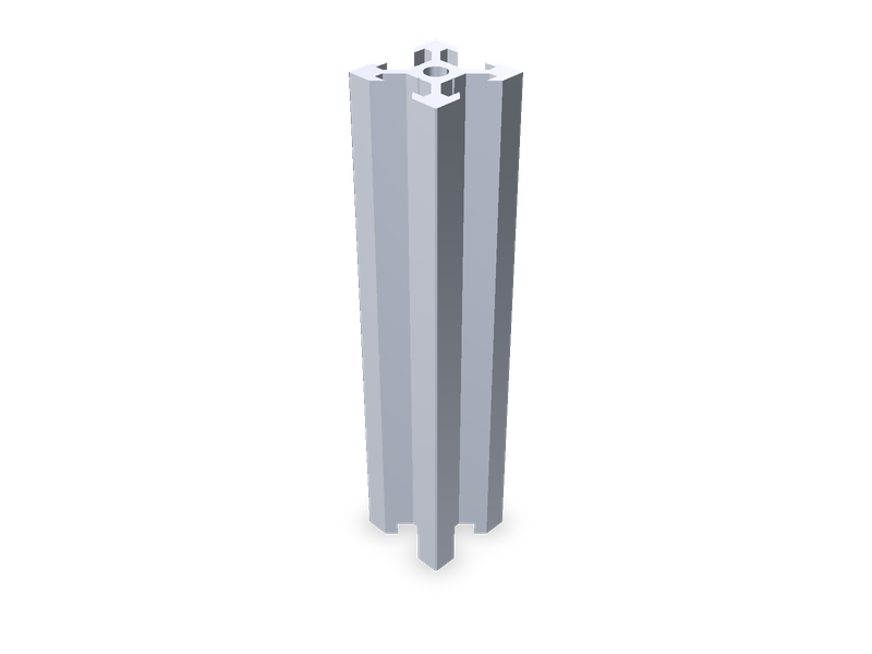
20 x 20 V-slot aluminium extrusion, any length, measured from the published FreeCAD-library model.
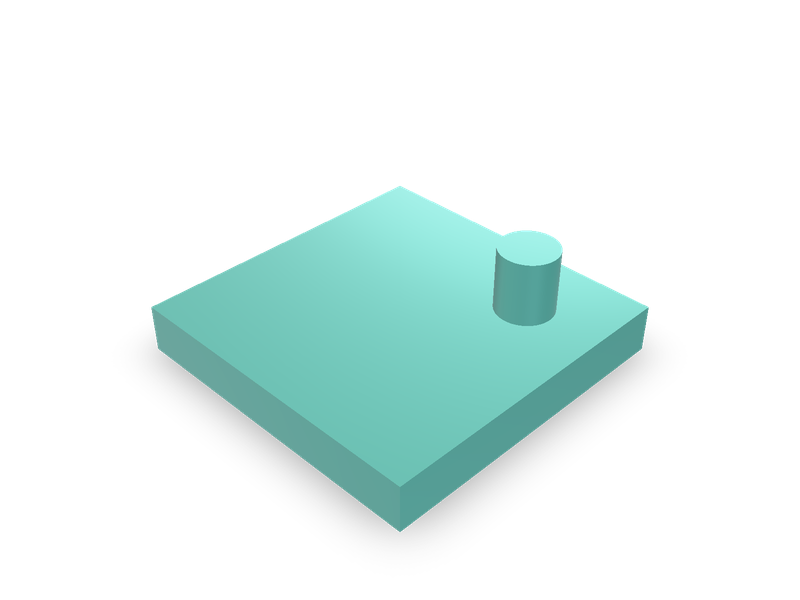
T-slot extrusion accessories (end cap, cover strip, anchor fastener, inside corner connector), 20/30/40 series: simplified.
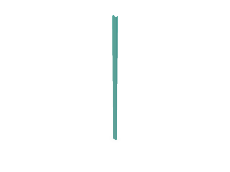
Light C channel (U channel), constant thickness, square corners, any size and length.