
STEVEMIT
steve/smd-electrolytic-capacitor
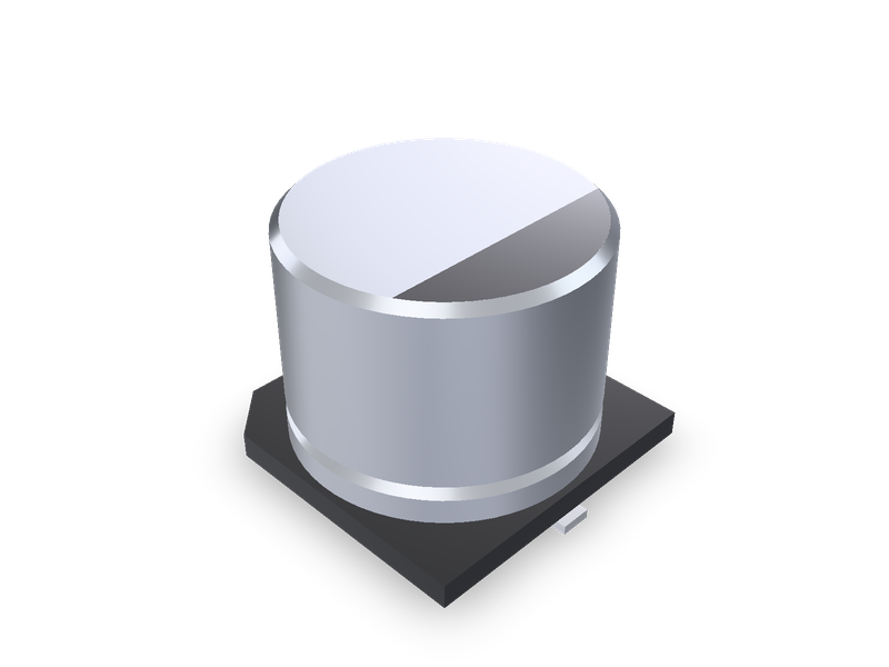
SMD aluminium electrolytic capacitors (chip type) by Nichicon series and case size: UZG, UZT, UWT, UCD and the bi-polar UWP and UUP, 4 x 3.9 to 10 x 10 mm.
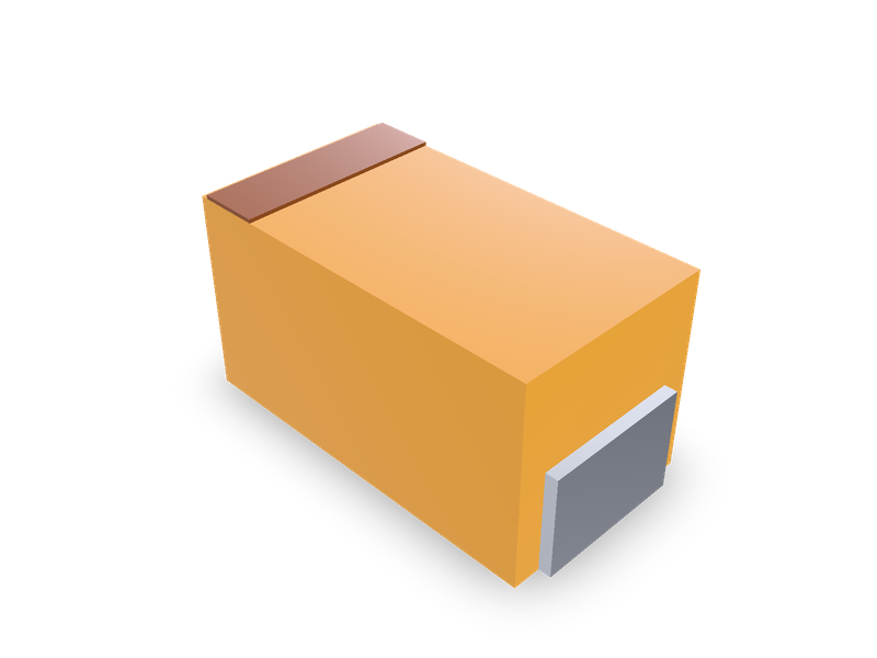
Moulded tantalum chip capacitors in KYOCERA AVX TAJ case sizes A to Y, standard and low profile, from AVX's TAJ data sheet.
| 1 | """Moulded tantalum chip capacitor, KYOCERA AVX TAJ case sizes, standard (A, B, C, D, E, U, V) and low profile (F, H, K, P, R, S, T, W, X, |
| 2 | Y). Centred on the origin with the board on the XY plane and the length along X: the moulded body, the polarity band on top at the anode |
| 3 | (-X) end, and a J-lead termination at each end that runs up the end face and under the body (each its own solid). Dimensions from AVX's |
| 4 | TAJ data sheet; see the README.""" |
| 5 | from steve import Model |
| 6 | |
| 7 | case = "A" # AVX case code |
| 8 | |
| 9 | # case: (EIA code, EIA metric code, profile, L, W, H, W1, A, S min.) in mm, the nominal values of AVX's tables. |
| 10 | # AVX "TAJ Series, Standard and Low Profile Tantalum Capacitors", catalogue issue 070417, page 6, "STANDARD CASE DIMENSIONS" and "LOW |
| 11 | # PROFILE CASE DIMENSIONS: millimeters (inches)". L is +/- 0.20, W +0.20 / -0.10, H +0.20 / -0.10 (standard; low profile: H max.), W1 |
| 12 | # +/- 0.20 (P and R: 1.00 +/- 0.10), A +0.30 / -0.20. "W1 dimension applies to the termination width for A dimensional area only." |
| 13 | CASES = { |
| 14 | "A": ("1206", "3216-18", "standard", 3.20, 1.60, 1.60, 1.20, 0.80, 1.10), |
| 15 | "B": ("1210", "3528-21", "standard", 3.50, 2.80, 1.90, 2.20, 0.80, 1.40), |
| 16 | "C": ("2312", "6032-28", "standard", 6.00, 3.20, 2.60, 2.20, 1.30, 2.90), |
| 17 | "D": ("2917", "7343-31", "standard", 7.30, 4.30, 2.90, 2.40, 1.30, 4.40), |
| 18 | "E": ("2917", "7343-43", "standard", 7.30, 4.30, 4.10, 2.40, 1.30, 4.40), |
| 19 | "U": ("2924", "7361-43", "standard", 7.30, 6.10, 4.10, 3.10, 1.30, 4.40), |
| 20 | "V": ("2924", "7361-38", "standard", 7.30, 6.10, 3.55, 3.10, 1.30, 4.40), |
| 21 | "F": ("2312", "6032-20", "low", 6.00, 3.20, 2.00, 2.20, 1.30, 2.90), |
| 22 | "H": ("1210", "3528-15", "low", 3.50, 2.80, 1.50, 2.20, 0.80, 1.40), |
| 23 | "K": ("1206", "3216-10", "low", 3.20, 1.60, 1.00, 1.20, 0.80, 1.10), |
| 24 | "P": ("0805", "2012-15", "low", 2.05, 1.35, 1.50, 1.00, 0.50, 0.85), |
| 25 | "R": ("0805", "2012-12", "low", 2.05, 1.30, 1.20, 1.00, 0.50, 0.85), |
| 26 | "S": ("1206", "3216-12", "low", 3.20, 1.60, 1.20, 1.20, 0.80, 1.10), |
| 27 | "T": ("1210", "3528-12", "low", 3.50, 2.80, 1.20, 2.20, 0.80, 1.40), |
| 28 | "W": ("2312", "6032-15", "low", 6.00, 3.20, 1.50, 2.20, 1.30, 2.90), |
| 29 | "X": ("2917", "7343-15", "low", 7.30, 4.30, 1.50, 2.40, 1.30, 4.40), |
| 30 | "Y": ("2917", "7343-20", "low", 7.30, 4.30, 2.00, 2.40, 1.30, 4.40), |
| 31 | } |
| 32 | # The middle of each tolerance band: W and A are 0.05 over nominal (+0.20 / -0.10, +0.30 / -0.20), and so is a standard case's H; a low |
| 33 | # profile case's H is its maximum, the only value given. |
| 34 | W_MID = 0.05 |
| 35 | H_MID = 0.05 |
| 36 | A_MID = 0.05 |
| 37 | # Proportions, for looks (the drawing shows these but don't dimension them): the termination's metal is LEAD thick; it covers the end face |
| 38 | # up to UP of the height, outside the moulding (which is 2 x LEAD shorter than L), and lies in a recess under it for A from the end. The |
| 39 | # polarity band is BAND_W of the length wide and BAND_IN of it in from the anode end; it stands BAND_T proud of the moulding, whose top is |
| 40 | # BAND_T under H. |
| 41 | LEAD = 0.1 |
| 42 | UP = 0.5 |
| 43 | BAND_W = 0.15 |
| 44 | BAND_IN = 0.05 |
| 45 | BAND_T = 0.03 |
| 46 | |
| 47 | eia, metric, profile, L, W, H, W1, A, S_MIN = CASES[case] |
| 48 | width, length_a = W + W_MID, A + A_MID |
| 49 | height = H + H_MID if profile == "standard" else H |
| 50 | model = Model() |
| 51 | model.box("body", L - 2 * LEAD, width, height - BAND_T, at=(0, 0, (height - BAND_T) / 2), op="new", body="body_body", name="Body") |
| 52 | leads = [] |
| 53 | for tag, side in (("anode", -1), ("cathode", 1)): |
| 54 | end = side * L / 2 |
| 55 | inner, wall = end - side * length_a, end - side * LEAD |
| 56 | # The termination's side section (x, z): up the end face to UP x height, and along the bottom A in from the end. |
| 57 | section = [(end, 0.0), (end, UP * height), (wall, UP * height), (wall, LEAD), (inner, LEAD), (inner, 0.0)] |
| 58 | # The XZ plane's normal is -Y: offset -W1 / 2 puts it on the termination's +Y side, and the extrusion runs across it to -Y. |
| 59 | model.plane(f"{tag}_plane", on="XZ", offset=-W1 / 2, name="Terminations") |
| 60 | with model.sketch(f"{tag}_sketch", on=f"{tag}_plane", name="Terminations") as sk: |
| 61 | sk.polyline(f"{tag}_section", section, closed=True) |
| 62 | model.extrude(f"{tag}_lead", f"{tag}_sketch", distance=W1, op="new", body=f"{tag}_body", name="Terminations") |
| 63 | # The recess under the moulding for the termination's foot, so that no solids overlap. |
| 64 | with model.sketch(f"{tag}_room_sketch", on=f"{tag}_plane", name="Room for the terminations") as sk: |
| 65 | sk.rect(f"{tag}_room", (min(inner, wall), 0.0), (max(inner, wall), LEAD)) |
| 66 | model.extrude(f"{tag}_room", f"{tag}_room_sketch", distance=W1, op="cut", body="body_body", name="Room for the terminations") |
| 67 | leads.append(f"{tag}_body") |
| 68 | band_x = -L / 2 + (BAND_IN + BAND_W / 2) * L |
| 69 | model.box("band", BAND_W * L, width, BAND_T, at=(band_x, 0, height - BAND_T / 2), op="new", body="band_body", name="Polarity band") |
| 70 | # Materials, for looks and a rough mass: the moulded case is epoxy compound, mostly silica filler (density about 1.9 to 2.0), ptfe (2.07) |
| 71 | # the nearest in the material list, in AVX's orange; the terminations are a tin-plated ("Sn Plating (standard)") lead frame, copper; the |
| 72 | # band is marking ink, shown in ptfe. |
| 73 | model.material("ptfe", bodies=["body_body"], color="#e8a33a") |
| 74 | model.material("ptfe", bodies=["band_body"], color="#8a4a22") |
| 75 | model.material("copper", bodies=leads, color="#c9ccd1") |
| 76 | result = model.result() |
| 77 |
| 1 | name = "steve/tantalum-chip-capacitor" |
| 2 | version = "1.0.1" |
| 3 | runtime = "steve" |
| 4 | license = "MIT" |
| 5 | summary = "Moulded tantalum chip capacitors in KYOCERA AVX TAJ case sizes A to Y, standard and low profile, from AVX's TAJ data sheet." |
| 6 | description = """Surface-mount moulded tantalum capacitors for board layouts and enclosures: the moulded case, the polarity band at the anode end and two J-lead terminations, each its own solid. Every case size of AVX's TAJ series: standard A, B, C, D, E, U and V, and low profile F, H, K, P, R, S, T, W, X and Y, by EIA size. Dimensions from AVX's data sheet. See the README.""" |
| 7 | tags = ["capacitor", "tantalum", "smd", "avx", "taj", "electronics"] |
| 8 | |
| 9 | [parameters.case] |
| 10 | type = "choice" |
| 11 | default = "A" |
| 12 | choices = ["A", "B", "C", "D", "E", "U", "V", "F", "H", "K", "P", "R", "S", "T", "W", "X", "Y"] |
| 13 | label = "Case" |
| 14 | description = "AVX case code. Standard: A 3216-18, B 3528-21, C 6032-28, D 7343-31, E 7343-43, U 7361-43, V 7361-38. Low profile: F 6032-20, H 3528-15, K 3216-10, P 2012-15, R 2012-12, S 3216-12, T 3528-12, W 6032-15, X 7343-15, Y 7343-20." |
| 15 | |
| 16 | [[presets]] |
| 17 | id = "A" |
| 18 | title = "Tantalum chip capacitor, AVX TAJ case A (EIA 3216-18, 1206), standard" |
| 19 | params = { case = "A" } |
| 20 | aliases = ["AVX case A", "TAJ case A", "EIA 3216-18", "EIA 1206 tantalum", "3216-18 tantalum capacitor"] |
| 21 | standard = "AVX TAJ" |
| 22 | |
| 23 | [[presets]] |
| 24 | id = "C" |
| 25 | title = "Tantalum chip capacitor, AVX TAJ case C (EIA 6032-28, 2312), standard" |
| 26 | params = { case = "C" } |
| 27 | aliases = ["AVX case C", "TAJ case C", "EIA 6032-28", "EIA 2312 tantalum", "6032-28 tantalum capacitor"] |
| 28 | standard = "AVX TAJ" |
| 29 | |
| 30 | [[presets]] |
| 31 | id = "D" |
| 32 | title = "Tantalum chip capacitor, AVX TAJ case D (EIA 7343-31, 2917), standard" |
| 33 | params = { case = "D" } |
| 34 | aliases = ["AVX case D", "TAJ case D", "EIA 7343-31", "EIA 2917 tantalum", "7343-31 tantalum capacitor"] |
| 35 | standard = "AVX TAJ" |
| 36 | |
| 37 | [[presets]] |
| 38 | id = "U" |
| 39 | title = "Tantalum chip capacitor, AVX TAJ case U (EIA 7361-43, 2924), standard" |
| 40 | params = { case = "U" } |
| 41 | aliases = ["AVX case U", "TAJ case U", "EIA 7361-43", "EIA 2924 tantalum", "7361-43 tantalum capacitor"] |
| 42 | standard = "AVX TAJ" |
| 43 | |
| 44 | [[presets]] |
| 45 | id = "V" |
| 46 | title = "Tantalum chip capacitor, AVX TAJ case V (EIA 7361-38, 2924), standard" |
| 47 | params = { case = "V" } |
| 48 | aliases = ["AVX case V", "TAJ case V", "EIA 7361-38", "EIA 2924 tantalum", "7361-38 tantalum capacitor"] |
| 49 | standard = "AVX TAJ" |
| 50 | |
| 51 | [[presets]] |
| 52 | id = "F" |
| 53 | title = "Tantalum chip capacitor, AVX TAJ case F (EIA 6032-20, 2312), low profile" |
| 54 | params = { case = "F" } |
| 55 | aliases = ["AVX case F", "TAJ case F", "EIA 6032-20", "EIA 2312 tantalum", "6032-20 tantalum capacitor"] |
| 56 | standard = "AVX TAJ" |
| 57 | |
| 58 | [[presets]] |
| 59 | id = "H" |
| 60 | title = "Tantalum chip capacitor, AVX TAJ case H (EIA 3528-15, 1210), low profile" |
| 61 | params = { case = "H" } |
| 62 | aliases = ["AVX case H", "TAJ case H", "EIA 3528-15", "EIA 1210 tantalum", "3528-15 tantalum capacitor"] |
| 63 | standard = "AVX TAJ" |
| 64 | |
| 65 | [[presets]] |
| 66 | id = "P" |
| 67 | title = "Tantalum chip capacitor, AVX TAJ case P (EIA 2012-15, 0805), low profile" |
| 68 | params = { case = "P" } |
| 69 | aliases = ["AVX case P", "TAJ case P", "EIA 2012-15", "EIA 0805 tantalum", "2012-15 tantalum capacitor"] |
| 70 | standard = "AVX TAJ" |
| 71 | |
| 72 | [[presets]] |
| 73 | id = "X" |
| 74 | title = "Tantalum chip capacitor, AVX TAJ case X (EIA 7343-15, 2917), low profile" |
| 75 | params = { case = "X" } |
| 76 | aliases = ["AVX case X", "TAJ case X", "EIA 7343-15", "EIA 2917 tantalum", "7343-15 tantalum capacitor"] |
| 77 | standard = "AVX TAJ" |
| 78 | |
| 79 | [[presets]] |
| 80 | id = "B" |
| 81 | title = "Tantalum chip capacitor, AVX TAJ case B (EIA 3528-21, 1210), standard" |
| 82 | params = { case = "B" } |
| 83 | aliases = ["AVX case B", "TAJ case B", "EIA 3528-21", "EIA 1210 tantalum", "3528-21 tantalum capacitor"] |
| 84 | standard = "AVX TAJ" |
| 85 | |
| 86 | [[presets]] |
| 87 | id = "E" |
| 88 | title = "Tantalum chip capacitor, AVX TAJ case E (EIA 7343-43, 2917), standard" |
| 89 | params = { case = "E" } |
| 90 | aliases = ["AVX case E", "TAJ case E", "EIA 7343-43", "EIA 2917 tantalum", "7343-43 tantalum capacitor"] |
| 91 | standard = "AVX TAJ" |
| 92 | |
| 93 | [[presets]] |
| 94 | id = "K" |
| 95 | title = "Tantalum chip capacitor, AVX TAJ case K (EIA 3216-10, 1206), low profile" |
| 96 | params = { case = "K" } |
| 97 | aliases = ["AVX case K", "TAJ case K", "EIA 3216-10", "EIA 1206 tantalum", "3216-10 tantalum capacitor"] |
| 98 | standard = "AVX TAJ" |
| 99 | |
| 100 | [[presets]] |
| 101 | id = "R" |
| 102 | title = "Tantalum chip capacitor, AVX TAJ case R (EIA 2012-12, 0805), low profile" |
| 103 | params = { case = "R" } |
| 104 | aliases = ["AVX case R", "TAJ case R", "EIA 2012-12", "EIA 0805 tantalum", "2012-12 tantalum capacitor"] |
| 105 | standard = "AVX TAJ" |
| 106 | |
| 107 | [[presets]] |
| 108 | id = "S" |
| 109 | title = "Tantalum chip capacitor, AVX TAJ case S (EIA 3216-12, 1206), low profile" |
| 110 | params = { case = "S" } |
| 111 | aliases = ["AVX case S", "TAJ case S", "EIA 3216-12", "EIA 1206 tantalum", "3216-12 tantalum capacitor"] |
| 112 | standard = "AVX TAJ" |
| 113 | |
| 114 | [[presets]] |
| 115 | id = "T" |
| 116 | title = "Tantalum chip capacitor, AVX TAJ case T (EIA 3528-12, 1210), low profile" |
| 117 | params = { case = "T" } |
| 118 | aliases = ["AVX case T", "TAJ case T", "EIA 3528-12", "EIA 1210 tantalum", "3528-12 tantalum capacitor"] |
| 119 | standard = "AVX TAJ" |
| 120 | |
| 121 | [[presets]] |
| 122 | id = "W" |
| 123 | title = "Tantalum chip capacitor, AVX TAJ case W (EIA 6032-15, 2312), low profile" |
| 124 | params = { case = "W" } |
| 125 | aliases = ["AVX case W", "TAJ case W", "EIA 6032-15", "EIA 2312 tantalum", "6032-15 tantalum capacitor"] |
| 126 | standard = "AVX TAJ" |
| 127 | |
| 128 | [[presets]] |
| 129 | id = "Y" |
| 130 | title = "Tantalum chip capacitor, AVX TAJ case Y (EIA 7343-20, 2917), low profile" |
| 131 | params = { case = "Y" } |
| 132 | aliases = ["AVX case Y", "TAJ case Y", "EIA 7343-20", "EIA 2917 tantalum", "7343-20 tantalum capacitor"] |
| 133 | standard = "AVX TAJ" |
| 134 |
Moulded tantalum chip capacitors in KYOCERA AVX's TAJ case sizes: standard A, B, C, D, E, U and V, and low profile F, H, K, P, R, S, T, W, X and Y. The capacitor is centred on the origin with the board on the XY plane and its length along X. It is the moulded case, the polarity band on top at the anode (+, -X) end, and a J-lead termination at each end. Each termination runs up the end face and under the case, and is its own solid.
AVX, "TAJ Series, Standard and Low Profile Tantalum Capacitors", catalogue issue 070417, page 6, "STANDARD CASE DIMENSIONS" and "LOW PROFILE CASE DIMENSIONS: millimeters (inches)". Copy hosted by Chip and Dip, https://static.chipdip.ru/lib/821/DOC012821570.pdf.
| Case | EIA | EIA metric | L | W | H | W1 | A | S min. |
|---|---|---|---|---|---|---|---|---|
| A | 1206 | 3216-18 | 3.20 | 1.60 | 1.60 | 1.20 | 0.80 | 1.10 |
| B | 1210 | 3528-21 | 3.50 | 2.80 | 1.90 | 2.20 | 0.80 | 1.40 |
| C | 2312 | 6032-28 | 6.00 | 3.20 | 2.60 | 2.20 | 1.30 | 2.90 |
| D | 2917 | 7343-31 | 7.30 | 4.30 | 2.90 | 2.40 | 1.30 | 4.40 |
| E | 2917 | 7343-43 | 7.30 | 4.30 | 4.10 | 2.40 | 1.30 | 4.40 |
| U | 2924 | 7361-43 | 7.30 | 6.10 | 4.10 | 3.10 | 1.30 | 4.40 |
| V | 2924 | 7361-38 | 7.30 | 6.10 | 3.55 | 3.10 | 1.30 | 4.40 |
| F | 2312 | 6032-20 | 6.00 | 3.20 | 2.00 max. | 2.20 | 1.30 | 2.90 |
| H | 1210 | 3528-15 | 3.50 | 2.80 | 1.50 max. | 2.20 | 0.80 | 1.40 |
| K | 1206 | 3216-10 | 3.20 | 1.60 | 1.00 max. | 1.20 | 0.80 | 1.10 |
| P | 0805 | 2012-15 | 2.05 | 1.35 | 1.50 max. | 1.00 ± 0.10 | 0.50 | 0.85 |
| R | 0805 | 2012-12 | 2.05 | 1.30 | 1.20 max. | 1.00 ± 0.10 | 0.50 | 0.85 |
| S | 1206 | 3216-12 | 3.20 | 1.60 | 1.20 max. | 1.20 | 0.80 | 1.10 |
| T | 1210 | 3528-12 | 3.50 | 2.80 | 1.20 max. | 2.20 | 0.80 | 1.40 |
| W | 2312 | 6032-15 | 6.00 | 3.20 | 1.50 max. | 2.20 | 1.30 | 2.90 |
| X | 2917 | 7343-15 | 7.30 | 4.30 | 1.50 max. | 2.40 | 1.30 | 4.40 |
| Y | 2917 | 7343-20 | 7.30 | 4.30 | 2.00 max. | 2.40 | 1.30 | 4.40 |
The tolerances: L ± 0.20, W + 0.20 / - 0.10, H + 0.20 / - 0.10 (standard cases), W1 ± 0.20 (P and R: ± 0.10), A + 0.30 / - 0.20. L is the length, W the width and H the height. W1 is the termination's width, and A its length under the case from the end. S is the smallest gap between the terminations. The table notes: "W1 dimension applies to the termination width for A dimensional area only."
The model uses the middle of each tolerance band. W and A are 0.05 over nominal, and so is a standard case's H. A low profile case's H is its maximum, the only value given.
Proportions, stated plainly. The drawing shows these but doesn't dimension them:
Materials. The moulded case is epoxy compound, mostly silica filler (density about 1.9 to 2.0), and ptfe (2.07) is the nearest in the material list. It is shown in AVX's orange. The terminations are a tin-plated lead frame ("Sn Plating (standard)"), shown as copper. The tantalum anode inside isn't modelled, so the model is much lighter than the part. The page gives no weight.
The old catalogue's CP_EIA-<metric>_<maker>-<case> entries each name an EIA case size, with AVX's or KEMET's case letter. The mapping is by the EIA case code, not by the letter: makers give the same EIA case different letters (EIA 7343-15 is KEMET's W and AVX's X), so a KEMET-named entry maps to AVX's case of the same EIA code. Their reference models are single solids. Each was measured (overall length x width x height) and compared with AVX's case of the same EIA metric code. An entry maps when its length and width are within 0.05 of AVX's nominal, and its height is within 0.05 of AVX's nominal or maximum height. The EIA code's last figure is the maximum height.
| Entry | Reference model | AVX case |
|---|---|---|
CP_EIA-2012-15_AVX-P |
2.05 x 1.35 x 1.5 | P |
CP_EIA-3216-18_Kemet-A |
3.2 x 1.6 x 1.8 | A (H max. 1.80) |
CP_EIA-3528-15_AVX-H |
3.5 x 2.8 x 1.5 | H |
CP_EIA-6032-20_AVX-F |
6.0 x 3.2 x 2.0 | F |
CP_EIA-6032-28_Kemet-C |
6.0 x 3.2 x 2.8 | C (H max. 2.80) |
CP_EIA-7343-15_Kemet-W |
7.3 x 4.3 x 1.5 | X |
CP_EIA-7343-31_Kemet-D |
7.3 x 4.3 x 3.1 | D (H max. 3.10) |
CP_EIA-7361-38_AVX-V |
7.3 x 6.1 x 3.55 | V |
CP_EIA-7361-438_AVX-U |
7.3 x 6.1 x 4.1 | U |
Left out, with the measured differences:
| Entry | Reference model | AVX's case of that EIA code |
|---|---|---|
CP_EIA-2012-12_Kemet-R |
2.0 x 1.2 x 1.2 | R: 2.05 x 1.30 x 1.2 max. (width 0.10 off) |
CP_EIA-3216-10_Kemet-I |
3.4 x 1.8 x 1.2 | K: 3.20 x 1.60 x 1.0 max. |
CP_EIA-3216-12_Kemet-S |
3.4 x 1.8 x 1.2 | S: 3.20 x 1.60 x 1.2 max. |
CP_EIA-3528-12_Kemet-T |
3.7 x 3.0 x 1.2 | T: 3.50 x 2.80 x 1.2 max. |
CP_EIA-6032-15_Kemet-U |
6.3 x 3.5 x 1.5 | W: 6.00 x 3.20 x 1.5 max. |
CP_EIA-7343-20_Kemet-V |
7.5 x 4.6 x 2.0 | Y: 7.30 x 4.30 x 2.0 max. |
CP_EIA-7343-43_Kemet-X |
7.6 x 4.6 x 4.3 | E: 7.30 x 4.30 x 4.10 |
CP_EIA-1608-08_AVX-J, CP_EIA-1608-10_AVX-L, CP_EIA-7343-30_AVX-N, CP_EIA-7343-40_Kemet-Y and CP_EIA-7360-38_Kemet-E have no case in AVX's TAJ table, so no table has been read for them yet.
Changed in 1.0.1: the README says plainly that entries map by EIA case code, and that makers give the same case different letters. The model is unchanged.
| 1 | # Tantalum chip capacitor |
| 2 | |
| 3 | Moulded tantalum chip capacitors in KYOCERA AVX's TAJ case sizes: standard A, B, C, D, E, U and V, and low profile F, H, K, P, R, S, T, W, X and Y. The capacitor is centred on the origin with the board on the XY plane and its length along X. It is the moulded case, the polarity band on top at the anode (+, -X) end, and a J-lead termination at each end. Each termination runs up the end face and under the case, and is its own solid. |
| 4 | |
| 5 | ## Source |
| 6 | |
| 7 | AVX, "TAJ Series, Standard and Low Profile Tantalum Capacitors", catalogue issue 070417, page 6, "STANDARD CASE DIMENSIONS" and "LOW PROFILE CASE DIMENSIONS: millimeters (inches)". Copy hosted by Chip and Dip, <https://static.chipdip.ru/lib/821/DOC012821570.pdf>. |
| 8 | |
| 9 | | Case | EIA | EIA metric | L | W | H | W1 | A | S min. | |
| 10 | |---|---|---|---|---|---|---|---|---| |
| 11 | | A | 1206 | 3216-18 | 3.20 | 1.60 | 1.60 | 1.20 | 0.80 | 1.10 | |
| 12 | | B | 1210 | 3528-21 | 3.50 | 2.80 | 1.90 | 2.20 | 0.80 | 1.40 | |
| 13 | | C | 2312 | 6032-28 | 6.00 | 3.20 | 2.60 | 2.20 | 1.30 | 2.90 | |
| 14 | | D | 2917 | 7343-31 | 7.30 | 4.30 | 2.90 | 2.40 | 1.30 | 4.40 | |
| 15 | | E | 2917 | 7343-43 | 7.30 | 4.30 | 4.10 | 2.40 | 1.30 | 4.40 | |
| 16 | | U | 2924 | 7361-43 | 7.30 | 6.10 | 4.10 | 3.10 | 1.30 | 4.40 | |
| 17 | | V | 2924 | 7361-38 | 7.30 | 6.10 | 3.55 | 3.10 | 1.30 | 4.40 | |
| 18 | | F | 2312 | 6032-20 | 6.00 | 3.20 | 2.00 max. | 2.20 | 1.30 | 2.90 | |
| 19 | | H | 1210 | 3528-15 | 3.50 | 2.80 | 1.50 max. | 2.20 | 0.80 | 1.40 | |
| 20 | | K | 1206 | 3216-10 | 3.20 | 1.60 | 1.00 max. | 1.20 | 0.80 | 1.10 | |
| 21 | | P | 0805 | 2012-15 | 2.05 | 1.35 | 1.50 max. | 1.00 ± 0.10 | 0.50 | 0.85 | |
| 22 | | R | 0805 | 2012-12 | 2.05 | 1.30 | 1.20 max. | 1.00 ± 0.10 | 0.50 | 0.85 | |
| 23 | | S | 1206 | 3216-12 | 3.20 | 1.60 | 1.20 max. | 1.20 | 0.80 | 1.10 | |
| 24 | | T | 1210 | 3528-12 | 3.50 | 2.80 | 1.20 max. | 2.20 | 0.80 | 1.40 | |
| 25 | | W | 2312 | 6032-15 | 6.00 | 3.20 | 1.50 max. | 2.20 | 1.30 | 2.90 | |
| 26 | | X | 2917 | 7343-15 | 7.30 | 4.30 | 1.50 max. | 2.40 | 1.30 | 4.40 | |
| 27 | | Y | 2917 | 7343-20 | 7.30 | 4.30 | 2.00 max. | 2.40 | 1.30 | 4.40 | |
| 28 | |
| 29 | The tolerances: L ± 0.20, W + 0.20 / - 0.10, H + 0.20 / - 0.10 (standard cases), W1 ± 0.20 (P and R: ± 0.10), A + 0.30 / - 0.20. L is the length, W the width and H the height. W1 is the termination's width, and A its length under the case from the end. S is the smallest gap between the terminations. The table notes: "W1 dimension applies to the termination width for A dimensional area only." |
| 30 | |
| 31 | The model uses the middle of each tolerance band. W and A are 0.05 over nominal, and so is a standard case's H. A low profile case's H is its maximum, the only value given. |
| 32 | |
| 33 | **Proportions, stated plainly.** The drawing shows these but doesn't dimension them: |
| 34 | |
| 35 | - The termination's metal is 0.1 thick. It covers the end face up to half the height, W1 wide there too, outside the moulding. The moulding is 0.2 shorter than L, so the length over the terminations is L. Under the case, the foot lies in a recess A long. |
| 36 | - The polarity band is 0.15 of the length wide and 0.05 of it in from the anode end. It stands 0.03 proud of the moulding, whose top is 0.03 under H. |
| 37 | - The case is a plain block; the moulding's draft isn't modelled. |
| 38 | |
| 39 | **Materials.** The moulded case is epoxy compound, mostly silica filler (density about 1.9 to 2.0), and ptfe (2.07) is the nearest in the material list. It is shown in AVX's orange. The terminations are a tin-plated lead frame ("Sn Plating (standard)"), shown as copper. The tantalum anode inside isn't modelled, so the model is much lighter than the part. The page gives no weight. |
| 40 | |
| 41 | ## Catalogue models |
| 42 | |
| 43 | The old catalogue's `CP_EIA-<metric>_<maker>-<case>` entries each name an EIA case size, with AVX's or KEMET's case letter. The mapping is by the EIA case code, not by the letter: makers give the same EIA case different letters (EIA 7343-15 is KEMET's W and AVX's X), so a KEMET-named entry maps to AVX's case of the same EIA code. Their reference models are single solids. Each was measured (overall length x width x height) and compared with AVX's case of the same EIA metric code. An entry maps when its length and width are within 0.05 of AVX's nominal, and its height is within 0.05 of AVX's nominal or maximum height. The EIA code's last figure is the maximum height. |
| 44 | |
| 45 | | Entry | Reference model | AVX case | |
| 46 | |---|---|---| |
| 47 | | `CP_EIA-2012-15_AVX-P` | 2.05 x 1.35 x 1.5 | P | |
| 48 | | `CP_EIA-3216-18_Kemet-A` | 3.2 x 1.6 x 1.8 | A (H max. 1.80) | |
| 49 | | `CP_EIA-3528-15_AVX-H` | 3.5 x 2.8 x 1.5 | H | |
| 50 | | `CP_EIA-6032-20_AVX-F` | 6.0 x 3.2 x 2.0 | F | |
| 51 | | `CP_EIA-6032-28_Kemet-C` | 6.0 x 3.2 x 2.8 | C (H max. 2.80) | |
| 52 | | `CP_EIA-7343-15_Kemet-W` | 7.3 x 4.3 x 1.5 | X | |
| 53 | | `CP_EIA-7343-31_Kemet-D` | 7.3 x 4.3 x 3.1 | D (H max. 3.10) | |
| 54 | | `CP_EIA-7361-38_AVX-V` | 7.3 x 6.1 x 3.55 | V | |
| 55 | | `CP_EIA-7361-438_AVX-U` | 7.3 x 6.1 x 4.1 | U | |
| 56 | |
| 57 | Left out, with the measured differences: |
| 58 | |
| 59 | | Entry | Reference model | AVX's case of that EIA code | |
| 60 | |---|---|---| |
| 61 | | `CP_EIA-2012-12_Kemet-R` | 2.0 x 1.2 x 1.2 | R: 2.05 x 1.30 x 1.2 max. (width 0.10 off) | |
| 62 | | `CP_EIA-3216-10_Kemet-I` | 3.4 x 1.8 x 1.2 | K: 3.20 x 1.60 x 1.0 max. | |
| 63 | | `CP_EIA-3216-12_Kemet-S` | 3.4 x 1.8 x 1.2 | S: 3.20 x 1.60 x 1.2 max. | |
| 64 | | `CP_EIA-3528-12_Kemet-T` | 3.7 x 3.0 x 1.2 | T: 3.50 x 2.80 x 1.2 max. | |
| 65 | | `CP_EIA-6032-15_Kemet-U` | 6.3 x 3.5 x 1.5 | W: 6.00 x 3.20 x 1.5 max. | |
| 66 | | `CP_EIA-7343-20_Kemet-V` | 7.5 x 4.6 x 2.0 | Y: 7.30 x 4.30 x 2.0 max. | |
| 67 | | `CP_EIA-7343-43_Kemet-X` | 7.6 x 4.6 x 4.3 | E: 7.30 x 4.30 x 4.10 | |
| 68 | |
| 69 | `CP_EIA-1608-08_AVX-J`, `CP_EIA-1608-10_AVX-L`, `CP_EIA-7343-30_AVX-N`, `CP_EIA-7343-40_Kemet-Y` and `CP_EIA-7360-38_Kemet-E` have no case in AVX's TAJ table, so no table has been read for them yet. |
| 70 | |
| 71 | Changed in 1.0.1: the README says plainly that entries map by EIA case code, and that makers give the same case different letters. The model is unchanged. |
| 72 |
Surface-mount moulded tantalum capacitors for board layouts and enclosures: the moulded case, the polarity band at the anode end and two J-lead terminations, each its own solid. Every case size of AVX's TAJ series: standard A, B, C, D, E, U and V, and low profile F, H, K, P, R, S, T, W, X and Y, by EIA size. Dimensions from AVX's data sheet. See the README.
Moulded tantalum chip capacitors in KYOCERA AVX's TAJ case sizes: standard A, B, C, D, E, U and V, and low profile F, H, K, P, R, S, T, W, X and Y. The capacitor is centred on the origin with the board on the XY plane and its length along X. It is the moulded case, the polarity band on top at the anode (+, -X) end, and a J-lead termination at each end. Each termination runs up the end face and under the case, and is its own solid.
AVX, "TAJ Series, Standard and Low Profile Tantalum Capacitors", catalogue issue 070417, page 6, "STANDARD CASE DIMENSIONS" and "LOW PROFILE CASE DIMENSIONS: millimeters (inches)". Copy hosted by Chip and Dip, https://static.chipdip.ru/lib/821/DOC012821570.pdf.
| Case | EIA | EIA metric | L | W | H | W1 | A | S min. |
|---|---|---|---|---|---|---|---|---|
| A | 1206 | 3216-18 | 3.20 | 1.60 | 1.60 | 1.20 | 0.80 | 1.10 |
| B | 1210 | 3528-21 | 3.50 | 2.80 | 1.90 | 2.20 | 0.80 | 1.40 |
| C | 2312 | 6032-28 | 6.00 | 3.20 | 2.60 | 2.20 | 1.30 | 2.90 |
| D | 2917 | 7343-31 | 7.30 | 4.30 | 2.90 | 2.40 | 1.30 | 4.40 |
| E | 2917 | 7343-43 | 7.30 | 4.30 | 4.10 | 2.40 | 1.30 | 4.40 |
| U | 2924 | 7361-43 | 7.30 | 6.10 | 4.10 | 3.10 | 1.30 | 4.40 |
| V | 2924 | 7361-38 | 7.30 | 6.10 | 3.55 | 3.10 | 1.30 | 4.40 |
| F | 2312 | 6032-20 | 6.00 | 3.20 | 2.00 max. | 2.20 | 1.30 | 2.90 |
| H | 1210 | 3528-15 | 3.50 | 2.80 | 1.50 max. | 2.20 | 0.80 | 1.40 |
| K | 1206 | 3216-10 | 3.20 | 1.60 | 1.00 max. | 1.20 | 0.80 | 1.10 |
| P | 0805 | 2012-15 | 2.05 | 1.35 | 1.50 max. | 1.00 ± 0.10 | 0.50 | 0.85 |
| R | 0805 | 2012-12 | 2.05 | 1.30 | 1.20 max. | 1.00 ± 0.10 | 0.50 | 0.85 |
| S | 1206 | 3216-12 | 3.20 | 1.60 | 1.20 max. | 1.20 | 0.80 | 1.10 |
| T | 1210 | 3528-12 | 3.50 | 2.80 | 1.20 max. | 2.20 | 0.80 | 1.40 |
| W | 2312 | 6032-15 | 6.00 | 3.20 | 1.50 max. | 2.20 | 1.30 | 2.90 |
| X | 2917 | 7343-15 | 7.30 | 4.30 | 1.50 max. | 2.40 | 1.30 | 4.40 |
| Y | 2917 | 7343-20 | 7.30 | 4.30 | 2.00 max. | 2.40 | 1.30 | 4.40 |
The tolerances: L ± 0.20, W + 0.20 / - 0.10, H + 0.20 / - 0.10 (standard cases), W1 ± 0.20 (P and R: ± 0.10), A + 0.30 / - 0.20. L is the length, W the width and H the height. W1 is the termination's width, and A its length under the case from the end. S is the smallest gap between the terminations. The table notes: "W1 dimension applies to the termination width for A dimensional area only."
The model uses the middle of each tolerance band. W and A are 0.05 over nominal, and so is a standard case's H. A low profile case's H is its maximum, the only value given.
Proportions, stated plainly. The drawing shows these but doesn't dimension them:
Materials. The moulded case is epoxy compound, mostly silica filler (density about 1.9 to 2.0), and ptfe (2.07) is the nearest in the material list. It is shown in AVX's orange. The terminations are a tin-plated lead frame ("Sn Plating (standard)"), shown as copper. The tantalum anode inside isn't modelled, so the model is much lighter than the part. The page gives no weight.
The old catalogue's CP_EIA-<metric>_<maker>-<case> entries each name an EIA case size, with AVX's or KEMET's case letter. The mapping is by the EIA case code, not by the letter: makers give the same EIA case different letters (EIA 7343-15 is KEMET's W and AVX's X), so a KEMET-named entry maps to AVX's case of the same EIA code. Their reference models are single solids. Each was measured (overall length x width x height) and compared with AVX's case of the same EIA metric code. An entry maps when its length and width are within 0.05 of AVX's nominal, and its height is within 0.05 of AVX's nominal or maximum height. The EIA code's last figure is the maximum height.
| Entry | Reference model | AVX case |
|---|---|---|
CP_EIA-2012-15_AVX-P |
2.05 x 1.35 x 1.5 | P |
CP_EIA-3216-18_Kemet-A |
3.2 x 1.6 x 1.8 | A (H max. 1.80) |
CP_EIA-3528-15_AVX-H |
3.5 x 2.8 x 1.5 | H |
CP_EIA-6032-20_AVX-F |
6.0 x 3.2 x 2.0 | F |
CP_EIA-6032-28_Kemet-C |
6.0 x 3.2 x 2.8 | C (H max. 2.80) |
CP_EIA-7343-15_Kemet-W |
7.3 x 4.3 x 1.5 | X |
CP_EIA-7343-31_Kemet-D |
7.3 x 4.3 x 3.1 | D (H max. 3.10) |
CP_EIA-7361-38_AVX-V |
7.3 x 6.1 x 3.55 | V |
CP_EIA-7361-438_AVX-U |
7.3 x 6.1 x 4.1 | U |
Left out, with the measured differences:
| Entry | Reference model | AVX's case of that EIA code |
|---|---|---|
CP_EIA-2012-12_Kemet-R |
2.0 x 1.2 x 1.2 | R: 2.05 x 1.30 x 1.2 max. (width 0.10 off) |
CP_EIA-3216-10_Kemet-I |
3.4 x 1.8 x 1.2 | K: 3.20 x 1.60 x 1.0 max. |
CP_EIA-3216-12_Kemet-S |
3.4 x 1.8 x 1.2 | S: 3.20 x 1.60 x 1.2 max. |
CP_EIA-3528-12_Kemet-T |
3.7 x 3.0 x 1.2 | T: 3.50 x 2.80 x 1.2 max. |
CP_EIA-6032-15_Kemet-U |
6.3 x 3.5 x 1.5 | W: 6.00 x 3.20 x 1.5 max. |
CP_EIA-7343-20_Kemet-V |
7.5 x 4.6 x 2.0 | Y: 7.30 x 4.30 x 2.0 max. |
CP_EIA-7343-43_Kemet-X |
7.6 x 4.6 x 4.3 | E: 7.30 x 4.30 x 4.10 |
CP_EIA-1608-08_AVX-J, CP_EIA-1608-10_AVX-L, CP_EIA-7343-30_AVX-N, CP_EIA-7343-40_Kemet-Y and CP_EIA-7360-38_Kemet-E have no case in AVX's TAJ table, so no table has been read for them yet.
Changed in 1.0.1: the README says plainly that entries map by EIA case code, and that makers give the same case different letters. The model is unchanged.
SMD aluminium electrolytic capacitors (chip type) by Nichicon series and case size: UZG, UZT, UWT, UCD and the bi-polar UWP and UUP, 4 x 3.9 to 10 x 10 mm.
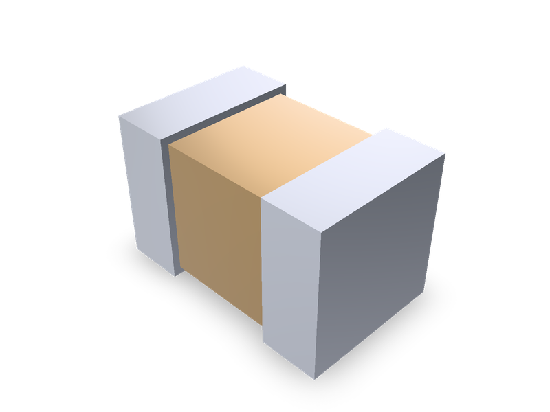
Multilayer ceramic chip capacitors (MLCC), EIA 01005 to 3640, with KEMET's and TDK's case dimensions and chip thickness codes.
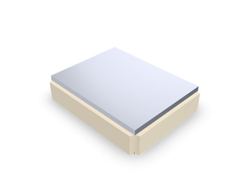
SMD quartz crystals by maker series: Epson FA-238, FA-238V, TSX-3225, MA-406, MA-505; TXC 7M, AX; Abracon ABM8G, ABM3B; EuroQuartz MT.
Molded SMD power inductors in the Sunlord MWSA-S sizes, 4.2 x 4.4 mm to 22 x 23.5 mm, by the maker's dimension table.