
STEVEMIT
steve/tht-tactile-switch
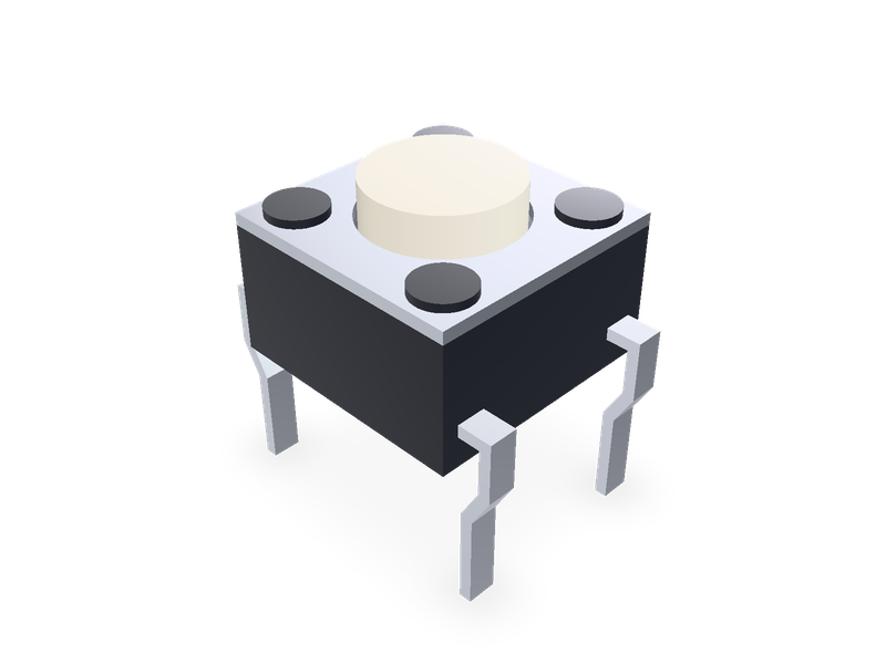
6 x 6 mm through-hole tactile switches from Omron's B3F data sheet: flat plungers 4.3 to 9.5 mm high, projected 7.3 mm, with or without a ground terminal.
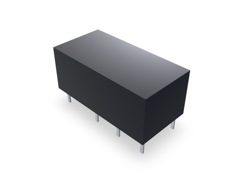
Through-hole PCB relays from the makers' data sheets: Omron, Finder, Schrack (TE), Tianbo HJR-4102, Hongfa HF115F and Sanyou SRD.
| 1 | """Through-hole PCB relay: Omron G2RL-2, G5V-1, G5V-2, G6A and G6AK; Finder 30.22, 32.21, 34.51, 36.11 and 40.31/51/52/61; Schrack (TE) |
| 2 | RT1, RT2 and RYII; Tianbo HJR-4102; Hongfa HF115F 2 pole; Sanyou SRD. A closed case on the XY plane with the pins down through the |
| 3 | board. Pin 1 is at the origin; the pins are placed as the maker's bottom-view PCB layout draws |
| 4 | them, seen from above (the layout turned over about its horizontal axis): along it to +X, its next row towards +Y. Dimensions from the |
| 5 | makers' data sheets in the README.""" |
| 6 | from steve import Model |
| 7 | |
| 8 | kind = "G6A" # Relay type |
| 9 | |
| 10 | # kind: (case length along X, width along Y, height above the board; solder pin length below the board, pin across X, pin across Y; |
| 11 | # pin 1 from the case's -X end, from its -Y side; pins (x, y) from pin 1, or (x, y, across X, across Y) for a pin of another section). |
| 12 | # Omron: the case sizes are the data sheets' average values. |
| 13 | # Omron G2RL, Cat. No. J117-E1-17, Dimensions p. 6, G2RL-2: 29 max. (28.8 average) x 12.7 max. (12.5) x 15.7 max. (15.5), terminals 3.5 long, |
| 14 | # 0.5 x 0.8; PCB mounting holes (bottom view): columns at 0, 15, 20, 25 (20 from pin 1 to the third, 5 apart), rows 7.5 apart, (2.3) from |
| 15 | # the case end and (2.5) from its side. Weight approx. 12 g (p. 2). |
| 16 | # Omron G5V-1, Cat. No. K048-E1-07, Dimensions p. 4: 12.5 max. (12.3) x 7.5 max. (7.3) x 10 max. (9.9), terminals 3.5 long, 0.5 x 0.3; |
| 17 | # holes at 0, 2.54 and 10.16, rows 5.08 apart, (1.07) and (1.11) from the case. Weight approx. 2 g. |
| 18 | # Omron G5V-2, Cat. No. K046-E1-06, Dimensions p. 4: 20.5 max. (20.3) x 10.1 max. (9.9) x 11.5 max. (11.4), terminals 3.5 long, |
| 19 | # 0.5 x 0.3; holes at 0, 7.62, 12.7, 17.78, rows 7.62 apart, (1.3) and (1.2) from the case. Weight approx. 5 g. |
| 20 | # Omron G6A, Cat. No. K020-E1-15, Dimensions p. 8: 20.2 max. (20) x 10.1 max. (9.9) x 8.4 max. (8.2), terminals 3.16 long, 0.6 x 0.3; |
| 21 | # G6A-274P: holes at 0, 7.62, 12.7, 17.78, rows 7.62 apart, (1.2) from the case; G6AK-274P (double-winding latching): also at 2.54, |
| 22 | # ten holes. Weight approx. 3.5 g (p. 2). |
| 23 | # Finder: pin 1 is coil terminal A1. The rows are centred across the case (the sheets dimension the rows and the case width, not the gap). |
| 24 | # Finder 30 series, edition II-2026 (S30EN): 30.22, copper side view p. 3: A1, 11, 12, 14 at 0, 7.62, 12.7, 17.78, rows 7.62 apart, 14 is 1.3 |
| 25 | # from the case end; outline drawing p. 5: 20.2 x 10 x 10.9, pins 3.2, coil pins 0.4, contact pins 0.6 along the case, 0.4 across. |
| 26 | # Finder 32 series, edition XII-2025 (S32EN): 32.21-4000 and -4300, copper side view p. 3: A1, 11, 14 at 0, 10.16, 17.78, A2 and 12 7.62 |
| 27 | # across, 14 is 1.1 from the case end; outline drawing p. 5: 20.2 x 10.1 x 10.7, pins 3.5, coil pins 0.4 x 0.4, contact pins 0.8 x 0.3. |
| 28 | # Finder 34 series, edition II-2026 (S34EN): 34.51, copper side view p. 3: one row, A2, A1, 12, 11, 14 at 0, 3.75, 15, 20, 25, 1.3 from the |
| 29 | # case side, 14 is 1.9 from the case end; outline drawing p. 9: 28 x 5 x 15, pins 3.5, coil pins 0.5 x 0.5, contact pins 1 x 0.4. |
| 30 | # Flat pack version 34.51.7xxx.x019, p. 6: the case lies on the board (28 x 15, 5 high), the pins bent down at its long side, the pin row |
| 31 | # 15.4 from the far side, the pin ends 7.5 from the case's top face (2.5 below the board). |
| 32 | # Finder 36 series, edition II-2026 (S36EN): 36.11-4011, copper side view p. 3: A1 and A2 6 + 6 apart, 11 between them 2 to the side and |
| 33 | # 1.2 from the case end, 14 and 12 12.2 from A1 and A2 and 3.4 from the other end; outline drawing p. 5: 18.8 x 15.2 x 15.5, pins 3.5, |
| 34 | # 11 0.3 x 1.2, coil pins 0.5 and contact pins 1 along the case (their thickness across isn't given: 0.5, as drawn). |
| 35 | # Finder 40 series, edition VIII-2026 (S40EN): copper side views p. 3: A1, A2 7.5 apart, 2.5 from the case end; 40.31: 12, 14 at 16.5, |
| 36 | # 23.5 in A1's row, 11 at 20 in A2's; 40.51: 15, 25 and 20; 40.52 and 40.61: 15, 20, 25 in both rows. Outline drawing p. 10: |
| 37 | # 29 x 12.4 x 25.1, pins 0.4 along the case, 1 across, 3.5 (PCB relay, "-3.5" here) or 5.2 (PCB or socket) long. |
| 38 | # Schrack (TE Connectivity): pin 1 is coil terminal A1. "PCB layout / terminal assignment, bottom view on solder pins". The sheets don't dimension |
| 39 | # the pins' section: 0.55 along the case and 1.0 (RT1, RT2) or 0.8 (RYII) across it, scaled from the outline drawings (line centres). |
| 40 | # Schrack RT1, datasheet 01-2020 Rev. 0120, p. 2 (layouts) and p. 3 (THT outline): 29.0 x 12.7 x 15.7, pins 3.6; rows 7.5 apart, 11 20.3 from A1 |
| 41 | # in A2's row, the case end 22.65 from 11; 12A 3.5 mm pinning (RT1 1x): 12 and 14 3.5 either side of 11, in A1's row; 12A 5 mm (RT2x): 5.04 |
| 42 | # either side; 16A 5 mm (RT3x): 12, 11, 14 in both rows. Form A (RTx3) leaves out 12. Weight 14 g (p. 2). |
| 43 | # Schrack RT2 (Asia/Pacific markets), datasheet 11-2020 Rev. 1120, p. 2: the RT1's case and pins; 8A 5 mm pinning, 12, 11, 14 and 22, 21, 24 at |
| 44 | # 15.26, 20.3, 25.34 (5.04 apart); 2 form A (RT44) leaves out 12 and 22. Weight 13 g. |
| 45 | # Schrack RY II, Datenblatt Rev. HC1, Ausgabe 2008/03, p. 2: 28.5 x 10.1 x 12.3, pins 3.2; 3.2 mm pinning (RY 21), A1 1.9 from the case end, |
| 46 | # 18.9 from A1 in A2's row, then 3.2 and 3.2 on, alternately in A1's and A2's rows; 5 mm pinning (RY 53, 1 Schliesser, and the 1 Oeffner on the |
| 47 | # same layout), A1 3.25 from the end, 18.9 in A1's row and 18.9 + 5.04 in A2's. Rows three grid steps of 2.5 to 2.54 apart (7.62 here). |
| 48 | # Weight 8 g (p. 2). |
| 49 | # Tianbo HJR-4102 (Ningbo Tianbo, TBO), data sheet "HJR4102" (Chip and Dip's copy, PDF of 2019-04), p. 3, overall and mounting dimensions: |
| 50 | # 15.7 x 10.4 x 11.7, pins 3.4; coil pins 0.3 square, 5 and 8 0.45 along the case, 6 and 7 0.4, all 0.3 across; holes: pin 1 and 12 (coil), |
| 51 | # then 10.16 and 2.54 on (5 and 6; 8 and 7), rows 7.62 apart. Form C (Z) and form A (H, without 7). Weight approx. 3.5 g (p. 1). |
| 52 | # The sheet doesn't place the pins in the case: the pattern is centred in it (1.5 from each end), as the side view draws it. |
| 53 | # Hongfa HF115F, data sheet 2025 Rev. 1.00 (source.hongfa.com HF115F_en.pdf), p. 221, outline, 5 mm pinning: 29 x 12.7 x 15.7, pins 3.6, |
| 54 | # coil pins 0.5 x 0.5, contact pins 0.5 x 0.8 (0.8 across the case); p. 222, PCB layout (bottom view), 5 mm pinning, 2 pole, 8 A |
| 55 | # (HF115F/xxx-2x-x-4): coil pins 2.6 from the case end, the contacts 20.16 from them and 5.04 either side, rows 7.56 apart; 2 form A (2H) |
| 56 | # keeps 20.16 and 25.2, 2 form B (2D) 15.12 and 20.16. Weight approx. 13.5 g (p. 219). |
| 57 | # Sanyou SRD, data sheet version V3.2 (LCSC's copy, atta.szlcsc.com), p. 3, outline: 19.6 x 15.4 x 15.5, pins 3.5; bottom view: the |
| 58 | # contacts 4.1 from the case end, 1 x 0.4; the coil 12.2 on, 0.55 square; the common 2.0 on and 1.3 from the other end, 0.3 x 1; |
| 59 | # rows 6 + 6 from the centre line, which the common sits on. Pin 1 is the common (the sheet numbers no pins); the layout is turned |
| 60 | # half a turn so that it's at the -X end. 1a (form A) keeps the contact on the -Y side, 1b (form B) the +Y one. Weight approx. 8.5 g (p. 1). |
| 61 | RELAYS = { |
| 62 | "G2RL-2": (28.8, 12.5, 15.5, 3.5, 0.5, 0.8, 2.3, 2.5, ((0, 0), (15, 0), (20, 0), (25, 0), (0, 7.5), (15, 7.5), (20, 7.5), (25, 7.5))), |
| 63 | "G5V-1": (12.3, 7.3, 9.9, 3.5, 0.5, 0.3, 1.07, 1.11, ((0, 0), (2.54, 0), (10.16, 0), (0, 5.08), (2.54, 5.08), (10.16, 5.08))), |
| 64 | "G5V-2": (20.3, 9.9, 11.4, 3.5, 0.5, 0.3, 1.3, 1.2, |
| 65 | ((0, 0), (7.62, 0), (12.7, 0), (17.78, 0), (0, 7.62), (7.62, 7.62), (12.7, 7.62), (17.78, 7.62))), |
| 66 | "G6A": (20.0, 9.9, 8.2, 3.16, 0.6, 0.3, 1.2, 1.2, |
| 67 | ((0, 0), (7.62, 0), (12.7, 0), (17.78, 0), (0, 7.62), (7.62, 7.62), (12.7, 7.62), (17.78, 7.62))), |
| 68 | "G6AK": (20.0, 9.9, 8.2, 3.16, 0.6, 0.3, 1.2, 1.2, |
| 69 | ((0, 0), (2.54, 0), (7.62, 0), (12.7, 0), (17.78, 0), (0, 7.62), (2.54, 7.62), (7.62, 7.62), (12.7, 7.62), (17.78, 7.62))), |
| 70 | "30.22": (20.2, 10.0, 10.9, 3.2, 0.6, 0.4, 1.12, 1.19, |
| 71 | ((0, 0, 0.4, 0.4), (7.62, 0), (12.7, 0), (17.78, 0), (0, 7.62, 0.4, 0.4), (7.62, 7.62), (12.7, 7.62), (17.78, 7.62))), |
| 72 | "32.21-4000": (20.2, 10.1, 10.7, 3.5, 0.8, 0.3, 1.32, 1.24, |
| 73 | ((0, 0, 0.4, 0.4), (10.16, 0), (17.78, 0), (0, 7.62, 0.4, 0.4), (17.78, 7.62))), |
| 74 | "32.21-4300": (20.2, 10.1, 10.7, 3.5, 0.8, 0.3, 1.32, 1.24, ((0, 0, 0.4, 0.4), (10.16, 0), (17.78, 0), (0, 7.62, 0.4, 0.4))), |
| 75 | "34.51": (28.0, 5.0, 15.0, 3.5, 1.0, 0.4, 4.85, 3.7, ((0, 0, 0.5, 0.5), (-3.75, 0, 0.5, 0.5), (11.25, 0), (16.25, 0), (21.25, 0))), |
| 76 | "34.51-flat": (28.0, 15.0, 5.0, 2.5, 1.0, 0.4, 4.85, -0.4, ((0, 0, 0.5, 0.5), (-3.75, 0, 0.5, 0.5), (11.25, 0), (16.25, 0), (21.25, 0))), |
| 77 | "36.11": (18.8, 15.2, 15.5, 3.5, 1.0, 0.5, 3.2, 1.6, ((0, 0, 0.5, 0.5), (12.2, 0), (-2, 6, 0.3, 1.2), (0, 12, 0.5, 0.5), (12.2, 12))), |
| 78 | "40.31": (29.0, 12.4, 25.1, 5.2, 0.4, 1.0, 2.5, 2.45, ((0, 0), (16.5, 0), (23.5, 0), (0, 7.5), (20, 7.5))), |
| 79 | "40.31-3.5": (29.0, 12.4, 25.1, 3.5, 0.4, 1.0, 2.5, 2.45, ((0, 0), (16.5, 0), (23.5, 0), (0, 7.5), (20, 7.5))), |
| 80 | "40.51": (29.0, 12.4, 25.1, 5.2, 0.4, 1.0, 2.5, 2.45, ((0, 0), (15, 0), (25, 0), (0, 7.5), (20, 7.5))), |
| 81 | "40.51-3.5": (29.0, 12.4, 25.1, 3.5, 0.4, 1.0, 2.5, 2.45, ((0, 0), (15, 0), (25, 0), (0, 7.5), (20, 7.5))), |
| 82 | "40.52": (29.0, 12.4, 25.1, 5.2, 0.4, 1.0, 2.5, 2.45, ((0, 0), (15, 0), (20, 0), (25, 0), (0, 7.5), (15, 7.5), (20, 7.5), (25, 7.5))), |
| 83 | "40.61": (29.0, 12.4, 25.1, 5.2, 0.4, 1.0, 2.5, 2.45, ((0, 0), (15, 0), (20, 0), (25, 0), (0, 7.5), (15, 7.5), (20, 7.5), (25, 7.5))), |
| 84 | "40.61-3.5": (29.0, 12.4, 25.1, 3.5, 0.4, 1.0, 2.5, 2.45, |
| 85 | ((0, 0), (15, 0), (20, 0), (25, 0), (0, 7.5), (15, 7.5), (20, 7.5), (25, 7.5))), |
| 86 | "RT11": (29.0, 12.7, 15.7, 3.6, 0.55, 1.0, 2.35, 2.6, ((0, 0), (16.8, 0), (23.8, 0), (0, 7.5), (20.3, 7.5))), |
| 87 | "RT13": (29.0, 12.7, 15.7, 3.6, 0.55, 1.0, 2.35, 2.6, ((0, 0), (23.8, 0), (0, 7.5), (20.3, 7.5))), |
| 88 | "RT21": (29.0, 12.7, 15.7, 3.6, 0.55, 1.0, 2.35, 2.6, ((0, 0), (15.26, 0), (25.34, 0), (0, 7.5), (20.3, 7.5))), |
| 89 | "RT23": (29.0, 12.7, 15.7, 3.6, 0.55, 1.0, 2.35, 2.6, ((0, 0), (25.34, 0), (0, 7.5), (20.3, 7.5))), |
| 90 | "RT31": (29.0, 12.7, 15.7, 3.6, 0.55, 1.0, 2.35, 2.6, |
| 91 | ((0, 0), (15.26, 0), (20.3, 0), (25.34, 0), (0, 7.5), (15.26, 7.5), (20.3, 7.5), (25.34, 7.5))), |
| 92 | "RT33": (29.0, 12.7, 15.7, 3.6, 0.55, 1.0, 2.35, 2.6, ((0, 0), (20.3, 0), (25.34, 0), (0, 7.5), (20.3, 7.5), (25.34, 7.5))), |
| 93 | "RT42": (29.0, 12.7, 15.7, 3.6, 0.55, 1.0, 2.35, 2.6, |
| 94 | ((0, 0), (15.26, 0), (20.3, 0), (25.34, 0), (0, 7.5), (15.26, 7.5), (20.3, 7.5), (25.34, 7.5))), |
| 95 | "RT44": (29.0, 12.7, 15.7, 3.6, 0.55, 1.0, 2.35, 2.6, ((0, 0), (20.3, 0), (25.34, 0), (0, 7.5), (20.3, 7.5), (25.34, 7.5))), |
| 96 | "RY21": (28.5, 10.1, 12.3, 3.2, 0.55, 0.8, 1.9, 1.24, ((0, 0), (22.1, 0), (0, 7.62), (18.9, 7.62), (25.3, 7.62))), |
| 97 | "RY53": (28.5, 10.1, 12.3, 3.2, 0.55, 0.8, 3.25, 1.24, ((0, 0), (18.9, 0), (0, 7.62), (23.94, 7.62))), |
| 98 | "RY5-NC": (28.5, 10.1, 12.3, 3.2, 0.55, 0.8, 3.25, 1.24, ((0, 0), (18.9, 0), (0, 7.62), (23.94, 7.62))), |
| 99 | "HJR-4102": (15.7, 10.4, 11.7, 3.4, 0.3, 0.3, 1.5, 1.39, |
| 100 | ((0, 0), (10.16, 0, 0.45, 0.3), (12.7, 0, 0.4, 0.3), (0, 7.62), (10.16, 7.62, 0.45, 0.3), (12.7, 7.62, 0.4, 0.3))), |
| 101 | "HJR-4102-A": (15.7, 10.4, 11.7, 3.4, 0.3, 0.3, 1.5, 1.39, |
| 102 | ((0, 0), (10.16, 0, 0.45, 0.3), (12.7, 0, 0.4, 0.3), (0, 7.62), (10.16, 7.62, 0.45, 0.3))), |
| 103 | "HF115F-2Z-4": (29.0, 12.7, 15.7, 3.6, 0.5, 0.8, 2.6, 2.57, |
| 104 | ((0, 0, 0.5, 0.5), (15.12, 0), (20.16, 0), (25.2, 0), (0, 7.56, 0.5, 0.5), (15.12, 7.56), (20.16, 7.56), (25.2, 7.56))), |
| 105 | "HF115F-2H-4": (29.0, 12.7, 15.7, 3.6, 0.5, 0.8, 2.6, 2.57, |
| 106 | ((0, 0, 0.5, 0.5), (20.16, 0), (25.2, 0), (0, 7.56, 0.5, 0.5), (20.16, 7.56), (25.2, 7.56))), |
| 107 | "HF115F-2D-4": (29.0, 12.7, 15.7, 3.6, 0.5, 0.8, 2.6, 2.57, |
| 108 | ((0, 0, 0.5, 0.5), (15.12, 0), (20.16, 0), (0, 7.56, 0.5, 0.5), (15.12, 7.56), (20.16, 7.56))), |
| 109 | "SRD-1C": (19.6, 15.4, 15.5, 3.5, 1.0, 0.4, 1.3, 7.7, ((0, 0, 0.3, 1.0), (2.0, -6, 0.55, 0.55), (2.0, 6, 0.55, 0.55), (14.2, -6), (14.2, 6))), |
| 110 | "SRD-1A": (19.6, 15.4, 15.5, 3.5, 1.0, 0.4, 1.3, 7.7, ((0, 0, 0.3, 1.0), (2.0, -6, 0.55, 0.55), (2.0, 6, 0.55, 0.55), (14.2, -6))), |
| 111 | "SRD-1B": (19.6, 15.4, 15.5, 3.5, 1.0, 0.4, 1.3, 7.7, ((0, 0, 0.3, 1.0), (2.0, -6, 0.55, 0.55), (2.0, 6, 0.55, 0.55), (14.2, 6))), |
| 112 | } |
| 113 | # Relays lying on the board with their pins bent down at the case's -Y side: kind: height of the pins' bend above the board (Finder 34.51 flat |
| 114 | # pack: the pins leave the case 1.3 from its face, the standing version's 1.3 from the case side, p. 3). |
| 115 | FLAT = {"34.51-flat": 1.3} |
| 116 | # Case colours, as the makers' pictures show them (black when not listed). |
| 117 | COLOURS = {"30.22": "#e9e7e1", "32.21-4000": "#e9e7e1", "32.21-4300": "#e9e7e1", "36.11": "#e9e7e1", "40.31": "#3f7fc4", "40.31-3.5": "#3f7fc4", |
| 118 | "40.51": "#3f7fc4", "40.51-3.5": "#3f7fc4", "40.52": "#3f7fc4", "40.61": "#3f7fc4", "40.61-3.5": "#3f7fc4", |
| 119 | "RT11": "#c4482f", "RT13": "#c4482f", "RT21": "#c4482f", "RT23": "#c4482f", "RT31": "#c4482f", "RT33": "#c4482f", |
| 120 | "RT42": "#d9d9d6", "RT44": "#d9d9d6", "RY21": "#e9e7e1", "RY53": "#e9e7e1", "RY5-NC": "#e9e7e1"} |
| 121 | # Proportions (the data sheets don't dimension the inside): the case is a cover WALL thick over a base plate as thick; the coil, core and contacts inside are one |
| 122 | # copper block filling FILL of the space inside the case, standing on its floor, so that the mass comes out near the data sheets' weights. |
| 123 | WALL = 0.5 |
| 124 | FILL = 0.27 |
| 125 | # Kinds whose block fills less, so that the mass comes out near the sheet's weight (HJR-4102 3.5 g, SRD 8.5 g). |
| 126 | FILLS = {"HJR-4102": 0.22, "HJR-4102-A": 0.22, "SRD-1C": 0.22, "SRD-1A": 0.22, "SRD-1B": 0.22} |
| 127 | |
| 128 | if kind not in RELAYS: |
| 129 | raise ValueError(f"no relay {kind!r}: {', '.join(RELAYS)}") |
| 130 | length, width, height, pin_length, pin_x, pin_y, from_end, from_side, pins = RELAYS[kind] |
| 131 | # Pin 1's place in the case: the PCB layouts' distances from pin 1 to the case's end and side (Omron: the bracketed reference values, the |
| 132 | # far end taking what's left of the average case size). |
| 133 | x0 = -from_end |
| 134 | y0 = -from_side |
| 135 | |
| 136 | model = Model() |
| 137 | # The case: a cover, open underneath, over a base plate WALL thick that closes it. |
| 138 | model.box("case", length, width, height, at=(x0 + length / 2, y0 + width / 2, height / 2), op="new", body="case_body", name="Cover") |
| 139 | inner = (length - 2 * WALL, width - 2 * WALL, height - 2 * WALL) |
| 140 | model.box("inside", inner[0], inner[1], height - WALL, at=(x0 + length / 2, y0 + width / 2, (height - WALL) / 2), op="cut", body="case_body", |
| 141 | name="Inside") |
| 142 | model.box("base", inner[0], inner[1], WALL, at=(x0 + length / 2, y0 + width / 2, WALL / 2), op="new", body="base_body", name="Base") |
| 143 | scale = FILLS.get(kind, FILL) ** (1 / 3) |
| 144 | core = (inner[0] * scale, inner[1] * scale, inner[2] * scale) |
| 145 | model.box("coil", core[0], core[1], core[2], at=(x0 + length / 2, y0 + width / 2, WALL + core[2] / 2), op="new", body="coil_body", |
| 146 | name="Coil and contacts") |
| 147 | bend = FLAT.get(kind) |
| 148 | pin_bodies = [] |
| 149 | for i, pin in enumerate(pins): |
| 150 | x, y = pin[0], pin[1] |
| 151 | sx, sy = (pin[2], pin[3]) if len(pin) == 4 else (pin_x, pin_y) |
| 152 | body = f"pin_{i + 1}_body" |
| 153 | if bend is None: |
| 154 | model.box(f"pin_{i + 1}", sx, sy, pin_length, at=(x, y, -pin_length / 2), op="new", body=body, name=f"Pin {i + 1}") |
| 155 | else: |
| 156 | # Bent pin: down through the board from the bend, and across to the case's side at the bend's height. |
| 157 | top = bend + sy / 2 |
| 158 | model.box(f"pin_{i + 1}", sx, sy, pin_length + top, at=(x, y, (top - pin_length) / 2), op="new", body=body, name=f"Pin {i + 1}") |
| 159 | model.box(f"pin_{i + 1}_leg", sx, y0 - y, sy, at=(x, (y0 + y) / 2, bend), op="join", body=body, name=f"Pin {i + 1} leg") |
| 160 | pin_bodies.append(body) |
| 161 | # Materials, for looks and a rough mass (the data sheets name none): a plastic case (pa6) in the maker's colour, the inside copper, tin-plated pins. |
| 162 | model.material("pa6", bodies=["case_body", "base_body"], color=COLOURS.get(kind, "#1d1e20")) |
| 163 | model.material("copper", bodies=["coil_body"], color="#b87333") |
| 164 | model.material("copper", bodies=pin_bodies, color="#c9cbc8") |
| 165 | result = model.result() |
| 166 |
| 1 | name = "steve/pcb-relay" |
| 2 | version = "1.3.0" |
| 3 | runtime = "steve" |
| 4 | license = "MIT" |
| 5 | summary = "Through-hole PCB relays from the makers' data sheets: Omron, Finder, Schrack (TE), Tianbo HJR-4102, Hongfa HF115F and Sanyou SRD." |
| 6 | description = """Through-hole PCB relay: a closed case on the board with its pins at the maker's PCB layout. Omron G2RL-2, G5V-1, G5V-2, G6A, G6AK. Finder 30.22, 32.21, 34.51 (standing or flat pack), 36.11, 40.31/51/52/61. Schrack (TE) RT1, RT2, RY II. Tianbo HJR-4102 (form C or A). Hongfa HF115F 2 pole, 8 A, 5 mm pinning (2 form C, A or B). Sanyou SRD (form C, A or B). Sizes and layouts from the makers' data sheets (README).""" |
| 7 | tags = ["relay", "pcb-relay", "power-relay", "through-hole", "omron", "finder", "schrack", "hongfa", "sanyou", "electronics"] |
| 8 | |
| 9 | [parameters.kind] |
| 10 | type = "choice" |
| 11 | default = "G6A" |
| 12 | choices = ["G2RL-2", "G5V-1", "G5V-2", "G6A", "G6AK", "30.22", "32.21-4000", "32.21-4300", "34.51", "34.51-flat", "36.11", "40.31", "40.31-3.5", "40.51", "40.51-3.5", "40.52", "40.61", "40.61-3.5", "RT11", "RT13", "RT21", "RT23", "RT31", "RT33", "RT42", "RT44", "RY21", "RY53", "RY5-NC", "HJR-4102", "HJR-4102-A", "HF115F-2Z-4", "HF115F-2H-4", "HF115F-2D-4", "SRD-1C", "SRD-1A", "SRD-1B"] |
| 13 | label = "Relay type" |
| 14 |
| 1 | # Presets of this part (factory/PRESETS.md). Written by factory/gen.py. |
| 2 | |
| 3 | [[presets]] |
| 4 | id = "G2RL-2" |
| 5 | title = "Omron G2RL-2, DPDT power relay" |
| 6 | params = { kind = "G2RL-2" } |
| 7 | aliases = ["Omron G2RL-2", "G2RL-2"] |
| 8 | standard = "Omron" |
| 9 | |
| 10 | [[presets]] |
| 11 | id = "G5V-1" |
| 12 | title = "Omron G5V-1, SPDT signal relay" |
| 13 | params = { kind = "G5V-1" } |
| 14 | aliases = ["Omron G5V-1", "G5V-1"] |
| 15 | standard = "Omron" |
| 16 | |
| 17 | [[presets]] |
| 18 | id = "G5V-2" |
| 19 | title = "Omron G5V-2, DPDT signal relay" |
| 20 | params = { kind = "G5V-2" } |
| 21 | aliases = ["Omron G5V-2", "G5V-2"] |
| 22 | standard = "Omron" |
| 23 | |
| 24 | [[presets]] |
| 25 | id = "G6A" |
| 26 | title = "Omron G6A, DPDT signal relay" |
| 27 | params = { kind = "G6A" } |
| 28 | aliases = ["Omron G6A", "G6A-274P"] |
| 29 | standard = "Omron" |
| 30 | |
| 31 | [[presets]] |
| 32 | id = "G6AK" |
| 33 | title = "Omron G6AK, DPDT signal relay, double-winding latching" |
| 34 | params = { kind = "G6AK" } |
| 35 | aliases = ["Omron G6AK", "G6AK-274P"] |
| 36 | standard = "Omron" |
| 37 | |
| 38 | [[presets]] |
| 39 | id = "30.22" |
| 40 | title = "Finder 30.22, DPDT signal relay, 2 A" |
| 41 | params = { kind = "30.22" } |
| 42 | aliases = ["Finder 30.22"] |
| 43 | standard = "Finder" |
| 44 | |
| 45 | [[presets]] |
| 46 | id = "32.21-4000" |
| 47 | title = "Finder 32.21-4000, SPDT relay, 6 A" |
| 48 | params = { kind = "32.21-4000" } |
| 49 | aliases = ["Finder 32.21-4000"] |
| 50 | standard = "Finder" |
| 51 | |
| 52 | [[presets]] |
| 53 | id = "32.21-4300" |
| 54 | title = "Finder 32.21-4300, SPST-NO relay, 6 A" |
| 55 | params = { kind = "32.21-4300" } |
| 56 | aliases = ["Finder 32.21-4300"] |
| 57 | standard = "Finder" |
| 58 | |
| 59 | [[presets]] |
| 60 | id = "34.51" |
| 61 | title = "Finder 34.51, SPDT ultra-slim relay, 6 A" |
| 62 | params = { kind = "34.51" } |
| 63 | aliases = ["Finder 34.51"] |
| 64 | standard = "Finder" |
| 65 | |
| 66 | [[presets]] |
| 67 | id = "34.51-flat" |
| 68 | title = "Finder 34.51-flat, SPDT ultra-slim relay, 6 A, flat pack" |
| 69 | params = { kind = "34.51-flat" } |
| 70 | aliases = ["Finder 34.51-flat"] |
| 71 | standard = "Finder" |
| 72 | |
| 73 | [[presets]] |
| 74 | id = "36.11" |
| 75 | title = "Finder 36.11, SPDT relay, 10 A" |
| 76 | params = { kind = "36.11" } |
| 77 | aliases = ["Finder 36.11", "Finder 36.11-4011"] |
| 78 | standard = "Finder" |
| 79 | |
| 80 | [[presets]] |
| 81 | id = "40.31" |
| 82 | title = "Finder 40.31, SPDT power relay, 12 A, 3.5 mm pitch, 5.2 mm pins" |
| 83 | params = { kind = "40.31" } |
| 84 | aliases = ["Finder 40.31"] |
| 85 | standard = "Finder" |
| 86 | |
| 87 | [[presets]] |
| 88 | id = "40.51" |
| 89 | title = "Finder 40.51, SPDT power relay, 12 A, 5 mm pitch, 5.2 mm pins" |
| 90 | params = { kind = "40.51" } |
| 91 | aliases = ["Finder 40.51"] |
| 92 | standard = "Finder" |
| 93 | |
| 94 | [[presets]] |
| 95 | id = "40.52" |
| 96 | title = "Finder 40.52, DPDT power relay, 8 A, 5.2 mm pins" |
| 97 | params = { kind = "40.52" } |
| 98 | aliases = ["Finder 40.52"] |
| 99 | standard = "Finder" |
| 100 | |
| 101 | [[presets]] |
| 102 | id = "RT21" |
| 103 | title = "Schrack RT21, RT1 SPDT power relay, 12 A, 5 mm pinning" |
| 104 | params = { kind = "RT21" } |
| 105 | aliases = ["Schrack RT21"] |
| 106 | standard = "Schrack" |
| 107 | |
| 108 | [[presets]] |
| 109 | id = "RT23" |
| 110 | title = "Schrack RT23, RT1 SPST-NO power relay, 12 A, 5 mm pinning" |
| 111 | params = { kind = "RT23" } |
| 112 | aliases = ["Schrack RT23"] |
| 113 | standard = "Schrack" |
| 114 | |
| 115 | [[presets]] |
| 116 | id = "RT33" |
| 117 | title = "Schrack RT33, RT1 SPST-NO power relay, 16 A, 5 mm pinning" |
| 118 | params = { kind = "RT33" } |
| 119 | aliases = ["Schrack RT33"] |
| 120 | standard = "Schrack" |
| 121 | |
| 122 | [[presets]] |
| 123 | id = "RT42" |
| 124 | title = "Schrack RT42, RT2 DPDT power relay, 8 A" |
| 125 | params = { kind = "RT42" } |
| 126 | aliases = ["Schrack RT42"] |
| 127 | standard = "Schrack" |
| 128 | |
| 129 | [[presets]] |
| 130 | id = "RT44" |
| 131 | title = "Schrack RT44, RT2 DPST-NO power relay, 8 A" |
| 132 | params = { kind = "RT44" } |
| 133 | aliases = ["Schrack RT44"] |
| 134 | standard = "Schrack" |
| 135 | |
| 136 | [[presets]] |
| 137 | id = "RY21" |
| 138 | title = "Schrack RY21, RY II SPDT relay, 8 A, 3.2 mm pinning" |
| 139 | params = { kind = "RY21" } |
| 140 | aliases = ["Schrack RY21"] |
| 141 | standard = "Schrack" |
| 142 | |
| 143 | [[presets]] |
| 144 | id = "RY53" |
| 145 | title = "Schrack RY53, RY II SPST-NO relay, 8 A, 5 mm pinning" |
| 146 | params = { kind = "RY53" } |
| 147 | aliases = ["Schrack RY53"] |
| 148 | standard = "Schrack" |
| 149 | |
| 150 | [[presets]] |
| 151 | id = "RY5-NC" |
| 152 | title = "Schrack RY5-NC, RY II SPST-NC relay, 8 A, 5 mm pinning" |
| 153 | params = { kind = "RY5-NC" } |
| 154 | aliases = ["Schrack RY5-NC"] |
| 155 | standard = "Schrack" |
| 156 | |
| 157 | [[presets]] |
| 158 | id = "HJR-4102" |
| 159 | title = "Tianbo HJR-4102, SPDT relay" |
| 160 | params = { kind = "HJR-4102" } |
| 161 | aliases = ["Tianbo HJR-4102", "HJR4102", "HJR-4102"] |
| 162 | standard = "Tianbo" |
| 163 | |
| 164 | [[presets]] |
| 165 | id = "HF115F-2Z-4" |
| 166 | title = "Hongfa HF115F-2Z-4, DPDT power relay, 8 A, 5 mm pinning" |
| 167 | params = { kind = "HF115F-2Z-4" } |
| 168 | aliases = ["Hongfa HF115F-2Z-4"] |
| 169 | standard = "Hongfa" |
| 170 | |
| 171 | [[presets]] |
| 172 | id = "SRD-1C" |
| 173 | title = "Sanyou SRD-1C, SPDT power relay" |
| 174 | params = { kind = "SRD-1C" } |
| 175 | aliases = ["Sanyou SRD-1C"] |
| 176 | standard = "Sanyou" |
| 177 | |
| 178 | [[presets]] |
| 179 | id = "SRD-1A" |
| 180 | title = "Sanyou SRD-1A, SPST-NO power relay" |
| 181 | params = { kind = "SRD-1A" } |
| 182 | aliases = ["Sanyou SRD-1A"] |
| 183 | standard = "Sanyou" |
| 184 | |
| 185 | [[presets]] |
| 186 | id = "SRD-1B" |
| 187 | title = "Sanyou SRD-1B, SPST-NC power relay" |
| 188 | params = { kind = "SRD-1B" } |
| 189 | aliases = ["Sanyou SRD-1B"] |
| 190 | standard = "Sanyou" |
| 191 | |
| 192 | [[presets]] |
| 193 | id = "40.31-3.5" |
| 194 | title = "Finder 40.31-3.5, SPDT power relay, 12 A, 3.5 mm pitch, 3.5 mm PCB pins" |
| 195 | params = { kind = "40.31-3.5" } |
| 196 | aliases = ["Finder 40.31-3.5"] |
| 197 | standard = "Finder" |
| 198 | |
| 199 | [[presets]] |
| 200 | id = "40.51-3.5" |
| 201 | title = "Finder 40.51-3.5, SPDT power relay, 12 A, 5 mm pitch, 3.5 mm PCB pins" |
| 202 | params = { kind = "40.51-3.5" } |
| 203 | aliases = ["Finder 40.51-3.5"] |
| 204 | standard = "Finder" |
| 205 | |
| 206 | [[presets]] |
| 207 | id = "40.61" |
| 208 | title = "Finder 40.61, SPDT power relay, 16 A, 5.2 mm pins" |
| 209 | params = { kind = "40.61" } |
| 210 | aliases = ["Finder 40.61"] |
| 211 | standard = "Finder" |
| 212 | |
| 213 | [[presets]] |
| 214 | id = "40.61-3.5" |
| 215 | title = "Finder 40.61-3.5, SPDT power relay, 16 A, 3.5 mm PCB pins" |
| 216 | params = { kind = "40.61-3.5" } |
| 217 | aliases = ["Finder 40.61-3.5"] |
| 218 | standard = "Finder" |
| 219 | |
| 220 | [[presets]] |
| 221 | id = "RT11" |
| 222 | title = "Schrack RT11, RT1 SPDT power relay, 12 A, 3.5 mm pinning" |
| 223 | params = { kind = "RT11" } |
| 224 | aliases = ["Schrack RT11"] |
| 225 | standard = "Schrack" |
| 226 | |
| 227 | [[presets]] |
| 228 | id = "RT13" |
| 229 | title = "Schrack RT13, RT1 SPST-NO power relay, 12 A, 3.5 mm pinning" |
| 230 | params = { kind = "RT13" } |
| 231 | aliases = ["Schrack RT13"] |
| 232 | standard = "Schrack" |
| 233 | |
| 234 | [[presets]] |
| 235 | id = "RT31" |
| 236 | title = "Schrack RT31, RT1 SPDT power relay, 16 A, 5 mm pinning" |
| 237 | params = { kind = "RT31" } |
| 238 | aliases = ["Schrack RT31"] |
| 239 | standard = "Schrack" |
| 240 | |
| 241 | [[presets]] |
| 242 | id = "HJR-4102-A" |
| 243 | title = "Tianbo HJR-4102-A, SPST-NO relay" |
| 244 | params = { kind = "HJR-4102-A" } |
| 245 | aliases = ["Tianbo HJR-4102-A"] |
| 246 | standard = "Tianbo" |
| 247 | |
| 248 | [[presets]] |
| 249 | id = "HF115F-2H-4" |
| 250 | title = "Hongfa HF115F-2H-4, DPST-NO power relay, 8 A, 5 mm pinning" |
| 251 | params = { kind = "HF115F-2H-4" } |
| 252 | aliases = ["Hongfa HF115F-2H-4"] |
| 253 | standard = "Hongfa" |
| 254 | |
| 255 | [[presets]] |
| 256 | id = "HF115F-2D-4" |
| 257 | title = "Hongfa HF115F-2D-4, DPST-NC power relay, 8 A, 5 mm pinning" |
| 258 | params = { kind = "HF115F-2D-4" } |
| 259 | aliases = ["Hongfa HF115F-2D-4"] |
| 260 | standard = "Hongfa" |
| 261 |
A through-hole PCB relay: a closed case on the board with its pins at the maker's PCB layout. Pin 1 is at the origin. The pins are placed as the maker's bottom-view PCB layout draws them, seen from above (the layout turned over about its horizontal axis). The layout's rows run along +X, and its next row is towards +Y. The pins go down through the board. The Finder 34.51 flat pack lies on the board, its pins bent down at one long side.
| Type | Contacts | Case (average) | Pins below the board | Pin section | PCB layout: columns from pin 1 | Rows apart | Pin 1 from the case end, side | Weight (sheet) |
|---|---|---|---|---|---|---|---|---|
| G2RL-2 | DPDT, power | 28.8 x 12.5 x 15.5 | 3.5 | 0.5 x 0.8 | 0, 15, 20, 25 | 7.5 | 2.3, 2.5 | approx. 12 g |
| G5V-1 | SPDT, signal | 12.3 x 7.3 x 9.9 | 3.5 | 0.5 x 0.3 | 0, 2.54, 10.16 | 5.08 | 1.07, 1.11 | approx. 2 g |
| G5V-2 | DPDT, signal | 20.3 x 9.9 x 11.4 | 3.5 | 0.5 x 0.3 | 0, 7.62, 12.7, 17.78 | 7.62 | 1.3, 1.2 | approx. 5 g |
| G6A | DPDT, signal | 20 x 9.9 x 8.2 | 3.16 | 0.6 x 0.3 | 0, 7.62, 12.7, 17.78 | 7.62 | 1.2, 1.2 | approx. 3.5 g |
| G6AK | DPDT, signal, double-winding latching | 20 x 9.9 x 8.2 | 3.16 | 0.6 x 0.3 | 0, 2.54, 7.62, 12.7, 17.78 | 7.62 | 1.2, 1.2 | approx. 3.5 g |
The case sizes are the data sheets' average values (their maximums are 0.2 to 0.3 larger). The distances from pin 1 to the case are the PCB layouts' bracketed reference values, and the case's far end takes what's left of its average size.
Omron data sheets, from Omron's own site (omronfs.omron.com/en_US/ecb/products/pdf/):
en-g2rl.pdf): weight approx. 12 g (Ratings, page 2); Dimensions, page 6, G2RL-2(-HA, -PW1), G2RL-24, G2RL-2-ASI: 29 max. (28.8) x 12.7 max. (12.5) x 15.7 max. (15.5), terminals 3.5 long, 0.5 and 0.8; PCB mounting holes: eight, 20 from pin 1 to the third column, the columns 5 apart, the rows 7.5 apart, (2.3) and (2.5) to the case.en-g5v_1.pdf): weight approx. 2 g; Dimensions, page 4: 12.5 max. (12.3) x 7.5 max. (7.3) x 10 max. (9.9), terminals 3.5, 0.5 and 0.3; six holes at 2.54, 7.62 (10.16 in all) and 5.08, (1.07) and (1.11) to the case.en-g5v_2.pdf): weight approx. 5 g; Dimensions, page 4: 20.5 max. (20.3) x 10.1 max. (9.9) x 11.5 max. (11.4), terminals 3.5, 0.5 and 0.3; eight holes at 7.62, 5.08, 5.08 and 7.62 apart, (1.3) and (1.2) to the case.en-g6a.pdf): weight approx. 3.5 g; Dimensions, page 8: G6A-274P and G6AU-274P, 20.2 max. (20) x 10.1 max. (9.9) x 8.4 max. (8.2), terminals 3.16 long, 0.6 and 0.3; eight holes at 7.62, 5.08, 5.08 and 7.62 apart, (1.2) to the case; G6AK-274P, ten holes, with a column 2.54 from pin 1.The data sheets name no materials.
Proportions, for looks and mass. The data sheets don't dimension the inside. The case is a cover 0.5 thick over a base plate 0.5 thick. The coil, core and contacts inside are one copper block filling 0.27 of the space inside the case and standing on the base. That share is the same for every type.
Mass, with pa6 at 1.15 and copper at 8.96 g/cm³:
| Type | Model | Data sheet |
|---|---|---|
| G2RL-2 | 12.4 g | approx. 12 g |
| G5V-1 | 1.85 g | approx. 2 g |
| G5V-2 | 4.94 g | approx. 5 g |
| G6A, G6AK | 3.45 g | approx. 3.5 g |
The case is black (pa6), and the pins are tin-plated copper.
Relay_DPDT_Omron_G6A and G6AK in the old catalogue were measured (2026-11-06): a case 20 x 9.9 x 8.2 with pins 3.16 below, pin 1 1.14 from the case's end and 1.21 from its side, against the sheet's (1.2) and (1.2). That's within 0.07, and the pins are at the same places. The catalogue's G2RL, G5V-1 and G5V-2 entries have no model. They name the part, and the sheets above give it.
Pin 1 is coil terminal A1. The sizes are the sheets' nominal values (they give no maximums).
| Type | Contacts | Case | Pins below the board | Pin section (along the case x across it) | PCB layout from A1 | Pin 1 from the case end, side |
|---|---|---|---|---|---|---|
| 30.22 | DPDT, 2 A | 20.2 x 10 x 10.9 | 3.2 | coil 0.4 x 0.4, contacts 0.6 x 0.4 | 11, 12, 14 at 7.62, 12.7, 17.78; A2 row 7.62 across | 1.12, 1.19 |
| 32.21-4000 | SPDT, 6 A | 20.2 x 10.1 x 10.7 | 3.5 | coil 0.4 x 0.4, contacts 0.8 x 0.3 | 11, 14 at 10.16, 17.78; A2 and 12 7.62 across | 1.32, 1.24 |
| 32.21-4300 | SPST-NO, 6 A | as 32.21-4000, without 12 | 3.5 | as above | as above | 1.32, 1.24 |
| 34.51 | SPDT, 6 A, 5 mm wide | 28 x 5 x 15 | 3.5 | coil 0.5 x 0.5, contacts 1 x 0.4 | one row: A2 at -3.75, 12, 11, 14 at 11.25, 16.25, 21.25 | 4.85, 3.7 |
| 34.51-flat | as 34.51, flat pack (34.51.7xxx.x019) | 28 x 15 lying, 5 high | 2.5 | as 34.51 | as 34.51, at the case's long side | 4.85, -0.4 (the case starts 0.4 past the pin row) |
| 36.11 | SPDT, 10 A (36.11-4011) | 18.8 x 15.2 x 15.5 | 3.5 | coil 0.5 x 0.5, 11 0.3 x 1.2, contacts 1 x 0.5 | A2 12 across; 11 at -2, 6 across; 14, 12 at 12.2 | 3.2, 1.6 |
| 40.31 | SPDT, 12 A, 3.5 mm pitch | 29 x 12.4 x 25.1 | 5.2 | 0.4 x 1 | 12, 14 at 16.5, 23.5; A2 7.5 across, 11 at 20 in its row | 2.5, 2.45 |
| 40.51 | SPDT, 12 A, 5 mm pitch | 29 x 12.4 x 25.1 | 5.2 | 0.4 x 1 | 12, 14 at 15, 25; 11 at 20 in A2's row | 2.5, 2.45 |
| 40.52 | DPDT, 8 A | 29 x 12.4 x 25.1 | 5.2 | 0.4 x 1 | 15, 20, 25 in both rows, 7.5 apart | 2.5, 2.45 |
| 40.61 | SPDT, 16 A | 29 x 12.4 x 25.1 | 5.2 | 0.4 x 1 | as 40.52 | 2.5, 2.45 |
40.31-3.5, 40.51-3.5 and 40.61-3.5 are the same relays with the 3.5 mm pins of the PCB-only versions (ordering code digit C = 2); the others have the 5.2 mm pins for PCB or sockets (40.52 comes only with those).
Finder series sheets, from Finder's own site (cdn.findernet.com/app/uploads/), with the edition printed on each page:
S30EN.pdf): copper side view, page 3: A1, 11, 12, 14 at 7.62, 5.08 and 5.08 apart, rows 7.62 apart, 14 1.3 from the case end, case 20.2 x 10; outline drawing, page 5: 20.2 x 10 x 10.9, pins 3.2 long, 0.4 (coil) and 0.6 (contacts) wide, 0.4 thick.S32EN.pdf): copper side views of 32.21-4000 and -4300, page 3: 10.16 and 7.62, rows 7.62 apart, 14 1.1 from the case end, case 20.2 x 10.1; outline drawing, page 5: 20.2 x 10.1 x 10.7, pins 3.5, 0.4 x 0.4 (coil) and 0.8 x 0.3 (contacts).S34EN.pdf): copper side view of 34.51, page 3: 3.75, 11.25, 5 and 5, the row 1.3 from the case side, 14 1.9 from the end, case 28 x 5; flat pack version, page 6: case 28 x 15, the pin row 15.4 from the far side, the pins' ends 7.5 from the case's far face; outline drawing, page 9: 28 x 5 x 15, pins 3.5, 0.5 x 0.5 and 1 x 0.4.S36EN.pdf): copper side view of 36.11-4011, page 3: 2, 12.2 and 3.4 along, 6 and 6 across, case 18.8 x 15.2; outline drawing, page 5: 18.8 x 15.2 x 15.5, pins 3.5, 0.3 x 1.2 (11), 0.5 (coil) and 1 (contacts) along the case.S40EN.pdf): copper side views, page 3: 2.5 and 20, 3.5 + 3.5 (40.31) or 5 + 5 (40.51, 40.52, 40.61), rows 7.5 apart, case 29 x 12.4; pin lengths 3.5 (PCB only) and 5.2 (PCB or socket), pages 3 and 5; outline drawing, page 10: 29 x 12.4 x 25.1, pins 0.4 x 1.The sheets name no materials and give no weight.
Proportions. The sheets dimension the rows and the case width but not the gap between them: the rows are centred across the case. The 36.11's coil and contact pins are taken as 0.5 thick across the case, as drawn (the sheet gives only their width along it). The small standoffs under the 32.21 (0.4) and 34.51 (0.3) cases aren't modelled: the case stands on the board. The flat pack's pins bend 1.3 above the board, the standing version's 1.3 from the case side. The inside is the Omron proportions: a 0.5 cover and base, and a copper block filling 0.27 of the inside.
Mass (no weight in the sheets to compare with): 30.22 4.75 g, 32.21 4.69 g, 34.51 4.39 g, 36.11 9.8 g, 40 series 20.2 to 20.3 g.
The 30, 32 and 36 cases are white, the 40 series' blue and the 34.51 black, as in Finder's pictures.
Measured 2026-11-06 against the sheets. The pin positions are the same in every model. The cases and pins differ:
| Model | Case (model / sheet) | Pin 1 from the case end (model / sheet) | Pins below (model / sheet) | Pin sections (model / sheet) |
|---|---|---|---|---|
Relay_DPDT_Finder_30.22 |
20.3 x 10.1 x 11.4 / 20.2 x 10 x 10.9 | 1.26 / 1.12 | 3.5 / 3.2 | all 0.7 x 0.4 / coil 0.4 x 0.4, contacts 0.6 x 0.4 |
Relay_SPDT_Finder_32.21-x000, Relay_SPST_Finder_32.21-x300 |
20 x 10 x 10.7 / 20.2 x 10.1 x 10.7 | 1.4 / 1.32 | 3.0 / 3.5 | contacts 0.6 x 0.4 / 0.8 x 0.3 |
Relay_SPDT_Finder_34.51_Vertical |
28 x 5 x 15, the same | 4.85, the same | 3.5, the same | the same |
Relay_SPDT_Finder_34.51_Horizontal |
28 x 15.85 (with the pins) x 5 / 28 x 15.4 x 5 | 4.85, the same | 3.0 / 2.5 | the same |
Relay_SPDT_Finder_36.11 |
19 x 15.2 x 15.5 / 18.8 x 15.2 x 15.5 (turned 90 degrees) | 3.4 / 3.2 | 3.5, the same | contacts 1 x 0.4 / 1 x 0.5 (thickness not given) |
Relay_SPDT_Finder_40.31, 40.51, Relay_DPDT_Finder_40.52 |
29 x 12.4 x 25 / 29 x 12.4 x 25.1 | 3.0 / 2.5 | 5.3 / 5.2 | the same |
The catalogue's x000 and x300 stand for 32.21-4000 and -4300, the only 32.21 types in the sheet. Its Finder_40.11 and 40.41 aren't in the 40 series sheet (edition VIII-2026), so they're left out.
Pin 1 is coil terminal A1. The kinds are the product codes' first letters and digits (RT114024 is an RT11, RT424024 an RT42, RY211024 an RY21).
| Type | Contacts | Case | Pins below the board | PCB layout from A1 (A2's row 7.5 across, RY II 7.62) | Pin 1 from the case end, side | Weight (sheet) | Model |
|---|---|---|---|---|---|---|---|
| RT11 | RT1 SPDT 12 A, 3.5 mm pinning | 29.0 x 12.7 x 15.7 | 3.6 | 12, 14 at 16.8, 23.8; 11 at 20.3 in A2's row | 2.35, 2.6 | 14 g | 12.85 g |
| RT13 | RT1 SPST-NO 12 A, 3.5 mm | as RT11 | 3.6 | 14 at 23.8; 11 at 20.3 in A2's row | 2.35, 2.6 | 14 g | 12.85 g |
| RT21 | RT1 SPDT 12 A, 5 mm pinning | as RT11 | 3.6 | 12, 14 at 15.26, 25.34; 11 at 20.3 in A2's row | 2.35, 2.6 | 14 g | 12.85 g |
| RT23 | RT1 SPST-NO 12 A, 5 mm | as RT11 | 3.6 | 14 at 25.34; 11 at 20.3 in A2's row | 2.35, 2.6 | 14 g | 12.85 g |
| RT31 | RT1 SPDT 16 A, 5 mm | as RT11 | 3.6 | 12, 11, 14 at 15.26, 20.3, 25.34 in both rows | 2.35, 2.6 | 14 g | 12.9 g |
| RT33 | RT1 SPST-NO 16 A, 5 mm | as RT11 | 3.6 | 11, 14 at 20.3, 25.34 in both rows | 2.35, 2.6 | 14 g | 12.87 g |
| RT42 | RT2 DPDT 8 A | as RT11 | 3.6 | 12, 11, 14 and 22, 21, 24 at 15.26, 20.3, 25.34 | 2.35, 2.6 | 13 g | 12.9 g |
| RT44 | RT2 DPST-NO 8 A | as RT11 | 3.6 | 11, 14 and 21, 24 at 20.3, 25.34 | 2.35, 2.6 | 13 g | 12.87 g |
| RY21 | RY II SPDT 8 A, 3.2 mm pinning | 28.5 x 10.1 x 12.3 | 3.2 | 22.1; 18.9 and 25.3 in A2's row | 1.9, 1.24 | 8 g | 7.72 g |
| RY53 | RY II SPST-NO 8 A, 5 mm pinning | as RY21 | 3.2 | 18.9; 23.94 in A2's row | 3.25, 1.24 | 8 g | 7.71 g |
| RY5-NC | RY II SPST-NC 8 A, 5 mm | as RY21 | 3.2 | as RY53 | 3.25, 1.24 | 8 g | 7.71 g |
Schrack data sheets by TE Connectivity, read from Chip and Dip's copies (static.chipdip.ru) and Conrad's (asset.conrad.com):
Proportions. The rows are centred across the case. The sheets don't dimension the pins: they are 0.55 along the case and 1.0 (RT1, RT2) or 0.8 (RY II) across it, scaled from the outline drawings (the outline's line centres, against its 29.0 or 28.5 and the 18.9 between pins). The RY II's rows are three steps of the sheet's 2.5 to 2.54 grid: 7.62 here. The inside is the Omron proportions. The RT1 comes out 8 % under its 14 g, the RT2 and RY II within 4 %.
The RT1 is red and the RT2 and RY II light grey and white, as in the sheets' pictures.
Measured 2026-11-06 (Relay_SPDT_Schrack-RT1-FormC_RM5mm, -RT1-FormA, -RT1-16A-FormA, Relay_DPDT_Schrack-RT2-FormC, Relay_DPST_Schrack-RT2-FormA, Relay_1-Form-C_Schrack-RYII_RM3.2mm, -Form-A_ and -Form-B_Schrack-RYII_RM5mm). The pins are at the sheets' places and the cases are the sheets' sizes and places. Two things differ: the models' pins reach 5.3 below the board against the sheets' 3.6 (RT1, RT2) and 3.2 (RY II), and they are 0.4 x 1.0, where the drawings scale to 0.55 x 1.0 and 0.55 x 0.8.
The catalogue's Relay_DPDT_Schrack-RT2-FormC-Dual-Coil_RM5mm waits for a sheet with the dual-coil RT2.
Pin 1 is coil terminal 1, as the sheet numbers it. HJR-4102 is form C (ordering code ...-S-Z), HJR-4102-A form A (...-H), without pin 7.
| Type | Contacts | Case | Pins below the board | Pin section (along the case x across it) | PCB layout from pin 1 | Pin 1 from the case end, side | Weight (sheet) | Model |
|---|---|---|---|---|---|---|---|---|
| HJR-4102 | SPDT | 15.7 x 10.4 x 11.7 | 3.4 | coil 0.3 x 0.3; 5 and 8 0.45 x 0.3; 6 and 7 0.4 x 0.3 | 5, 6 at 10.16, 12.7; 12, 8, 7 in the row 7.62 across | 1.5, 1.39 | approx. 3.5 g | 3.43 g |
| HJR-4102-A | SPST-NO | as HJR-4102 | 3.4 | as above | as above, without 7 | 1.5, 1.39 | approx. 3.5 g | 3.43 g |
Ningbo Tianbo (TBO), data sheet HJR4102 (通信继电器), read from Chip and Dip's copy (static.chipdip.ru/lib/163/DOC045163777.pdf; the PDF is dated 2019-04 and has no revision printed): ordering code and weight (approx. 3.5 g), page 1; overall and mounting dimensions, page 3: 15.7 x 10.4 x 11.7, pins 3.4; pins 0.3 thick, 0.3 (coil), 2-0.45 and 2-0.4 wide; six holes, 10.16 and 2.54 along, 7.62 across; wiring diagrams of form C and form A.
An older copy of the same sheet (static.chipdip.ru/lib/858/DOC029858842.pdf, document T810S-T002C) gives the case as 15.7 max. x 10.4 ±0.3 x 11.7 max., the pins 3.4 ±0.3, and the pins at 10.16 0.7 wide, not 0.45. The later sheet's values are used.
Proportions. The sheet doesn't place the pins in the case: the pattern is centred in it, 1.5 from each end (the side view draws it about 1.5 to 1.8 from the ends) and 1.39 from each side. The inside is the Omron proportions with a smaller block: it fills 0.22 of the inside, so that the mass comes out at the sheet's 3.5 g.
The case is black, as in the sheet's picture.
The old catalogue's Relay_SPDT_HJR-4102, measured 2026-11-06: the case 15.7 x 10.4 x 11.4 against the sheet's 11.7, pins 3.6 below against 3.4, all pins 0.3 x 0.3, pin 1 1.25 from the case end. Its 5 and 8 are at 9.86 from pin 1 and its 6 and 7 at 12.4, where the sheet puts them at 10.16 and 12.7: the model is wrong there, and the sheet's layout is used.
Pin 1 is a coil terminal. The 2 pole, 8 A, 5 mm pinning versions (HF115F/xxx-2xx-x-4xx): HF115F-2Z-4 2 form C, HF115F-2H-4 2 form A, HF115F-2D-4 2 form B.
| Type | Contacts | Case | Pins below the board | Pin section (along the case x across it) | PCB layout from pin 1 | Pin 1 from the case end, side | Weight (sheet) | Model |
|---|---|---|---|---|---|---|---|---|
| HF115F-2Z-4 | DPDT, 8 A | 29 x 12.7 x 15.7 | 3.6 | coil 0.5 x 0.5, contacts 0.5 x 0.8 | 15.12, 20.16, 25.2 in both rows, 7.56 apart | 2.6, 2.57 | approx. 13.5 g | 12.86 g |
| HF115F-2H-4 | DPST-NO, 8 A | as 2Z | 3.6 | as above | 20.16, 25.2 in both rows | 2.6, 2.57 | approx. 13.5 g | 12.83 g |
| HF115F-2D-4 | DPST-NC, 8 A | as 2Z | 3.6 | as above | 15.12, 20.16 in both rows | 2.6, 2.57 | approx. 13.5 g | 12.83 g |
Hongfa data sheet HF115F Miniature high power relay, 2025 Rev. 1.00, from Hongfa's own site (source.hongfa.com/Uploads/Product/PDF/HF115F_en.pdf), pages numbered 219 to 222: unit weight approx. 13.5 g, page 219; outline dimensions, 5 mm pinning, page 221: 29 ±0.3 x 12.7 ±0.3 x 15.7 ±0.3, pins 3.6 ±0.5, terminals 0.5 x 0.5 and 0.5 x 0.8 (3 terminals); PCB layout (bottom view), 5 mm pinning, 2 pole, 8 A, page 222: 2.6 from the case end to the coil pins, 20.16 to the middle contacts, 5.04 either side, rows 7.56 apart, for 2 form A, B and C.
Proportions. The rows are centred across the case. The case's 0.3 standoffs aren't modelled: it stands on the board. The inside is the Omron proportions; the model is 5 % under the sheet's weight.
The case is black, as in the sheet's picture.
The old catalogue's Relay_DPDT_Hongfa_HF115F-2Z-x4, measured 2026-11-06: the case 29 x 12.7 and pin sections as the sheet's, 15.8 high (with standoffs) against 15.7, pins 3.4 below against 3.6, pin 1 2.54 from the case end and 2.54 from its side against 2.6 and 2.57. Its first contact column is at 15.2 against the sheet's 15.12 (20.16 less 5.04), 0.08 off: the sheet's layout is used.
Pin 1 is the common contact (the sheet numbers no pins). The sheet's bottom view, turned over and then half a turn, so that the common is at the case's -X end: the coil pins 2.0 on, 6 either side of the common's line, and the contacts 12.2 further on, 6 either side. SRD-1C is form C (the sheet's 1c), SRD-1A form A (1a: the contact on the -Y side), SRD-1B form B (1b: on the +Y side). The SRD-DM, SRD-D and SRD-DB ratings share the case.
| Type | Contacts | Case | Pins below the board | Pin section (along the case x across it) | Pin 1 from the case end, side | Weight (sheet) | Model |
|---|---|---|---|---|---|---|---|
| SRD-1C | SPDT | 19.6 x 15.4 x 15.5 | 3.5 | common 0.3 x 1; coil 0.55 x 0.55; contacts 1 x 0.4 | 1.3, 7.7 | approx. 8.5 g | 8.62 g |
| SRD-1A | SPST-NO | as SRD-1C | 3.5 | as above | 1.3, 7.7 | approx. 8.5 g | 8.61 g |
| SRD-1B | SPST-NC | as SRD-1C | 3.5 | as above | 1.3, 7.7 | approx. 8.5 g | 8.61 g |
Sanyou Relays, data sheet SRD-Series Miniature Power Relay, version V3.2, read from LCSC's copy (atta.szlcsc.com/upload/public/pdf/source/231023/SRD.pdf-ba91e5635ca2ace5c4c74973894313b7.pdf): unit weight approx. 8.5 g, page 1; outline dimensions, page 3: 19.6 x 15.4 x 15.5, pins 3.5; bottom view: 4.1, 12.2, 2.0 and 1.3 along the case, rows 6 and 6 from the centre line, 1.7 from the side, pins 1 wide and 2-0.4 thick (contacts), 2-□0.55 (coil), 0.3 and 1 (common); PCB layouts 1c, 1b and 1a (bottom view), page 3.
Proportions. The inside is the Omron proportions with a smaller block: it fills 0.22 of the inside, so that the mass comes out at the sheet's 8.5 g.
The case is black, as in the sheet's picture.
The old catalogue's Relay_SPDT_SANYOU_SRD_Series_Form_C, Relay_SPST_SANYOU_SRD_Series_Form_A and _Form_B, measured 2026-11-06: the pins at the sheet's places and the case at its size and place, turned the same way, with form A's contact on the -Y side and form B's on the +Y side. They differ in the case's height (15.6 against 15.5), the pins below the board (3.4 against 3.5), the coil pins (0.5 square against 0.55) and the contact pins (1 x 0.3 against 1 x 0.4).
Panasonic, Fujitsu, Kemet, COTO, CUI, Standex-Meder, HsinDa and Omron G6H, G6K, G6S, G6E, G5LE and G5NB aren't here yet; see COVERAGE.md.
| 1 | # PCB relay, through-hole |
| 2 | |
| 3 | A through-hole PCB relay: a closed case on the board with its pins at the maker's PCB layout. Pin 1 is at the origin. The pins are placed as the maker's bottom-view PCB layout draws them, seen from above (the layout turned over about its horizontal axis). The layout's rows run along +X, and its next row is towards +Y. The pins go down through the board. The Finder 34.51 flat pack lies on the board, its pins bent down at one long side. |
| 4 | |
| 5 | ## Omron |
| 6 | |
| 7 | | Type | Contacts | Case (average) | Pins below the board | Pin section | PCB layout: columns from pin 1 | Rows apart | Pin 1 from the case end, side | Weight (sheet) | |
| 8 | |---|---|---|---|---|---|---|---|---| |
| 9 | | G2RL-2 | DPDT, power | 28.8 x 12.5 x 15.5 | 3.5 | 0.5 x 0.8 | 0, 15, 20, 25 | 7.5 | 2.3, 2.5 | approx. 12 g | |
| 10 | | G5V-1 | SPDT, signal | 12.3 x 7.3 x 9.9 | 3.5 | 0.5 x 0.3 | 0, 2.54, 10.16 | 5.08 | 1.07, 1.11 | approx. 2 g | |
| 11 | | G5V-2 | DPDT, signal | 20.3 x 9.9 x 11.4 | 3.5 | 0.5 x 0.3 | 0, 7.62, 12.7, 17.78 | 7.62 | 1.3, 1.2 | approx. 5 g | |
| 12 | | G6A | DPDT, signal | 20 x 9.9 x 8.2 | 3.16 | 0.6 x 0.3 | 0, 7.62, 12.7, 17.78 | 7.62 | 1.2, 1.2 | approx. 3.5 g | |
| 13 | | G6AK | DPDT, signal, double-winding latching | 20 x 9.9 x 8.2 | 3.16 | 0.6 x 0.3 | 0, 2.54, 7.62, 12.7, 17.78 | 7.62 | 1.2, 1.2 | approx. 3.5 g | |
| 14 | |
| 15 | The case sizes are the data sheets' average values (their maximums are 0.2 to 0.3 larger). The distances from pin 1 to the case are the PCB layouts' bracketed reference values, and the case's far end takes what's left of its average size. |
| 16 | |
| 17 | ## Source |
| 18 | |
| 19 | Omron data sheets, from Omron's own site (omronfs.omron.com/en_US/ecb/products/pdf/): |
| 20 | |
| 21 | - *PCB Power Relay G2RL*, Cat. No. J117-E1-17 (`en-g2rl.pdf`): weight approx. 12 g (Ratings, page 2); Dimensions, page 6, G2RL-2(-HA, -PW1), G2RL-24, G2RL-2-ASI: 29 max. (28.8) x 12.7 max. (12.5) x 15.7 max. (15.5), terminals 3.5 long, 0.5 and 0.8; PCB mounting holes: eight, 20 from pin 1 to the third column, the columns 5 apart, the rows 7.5 apart, (2.3) and (2.5) to the case. |
| 22 | - *Low Signal Relay G5V-1*, Cat. No. K048-E1-07 (`en-g5v_1.pdf`): weight approx. 2 g; Dimensions, page 4: 12.5 max. (12.3) x 7.5 max. (7.3) x 10 max. (9.9), terminals 3.5, 0.5 and 0.3; six holes at 2.54, 7.62 (10.16 in all) and 5.08, (1.07) and (1.11) to the case. |
| 23 | - *Low Signal Relay G5V-2*, Cat. No. K046-E1-06 (`en-g5v_2.pdf`): weight approx. 5 g; Dimensions, page 4: 20.5 max. (20.3) x 10.1 max. (9.9) x 11.5 max. (11.4), terminals 3.5, 0.5 and 0.3; eight holes at 7.62, 5.08, 5.08 and 7.62 apart, (1.3) and (1.2) to the case. |
| 24 | - *Low Signal Relay G6A*, Cat. No. K020-E1-15 (`en-g6a.pdf`): weight approx. 3.5 g; Dimensions, page 8: G6A-274P and G6AU-274P, 20.2 max. (20) x 10.1 max. (9.9) x 8.4 max. (8.2), terminals 3.16 long, 0.6 and 0.3; eight holes at 7.62, 5.08, 5.08 and 7.62 apart, (1.2) to the case; G6AK-274P, ten holes, with a column 2.54 from pin 1. |
| 25 | |
| 26 | The data sheets name no materials. |
| 27 | |
| 28 | **Proportions, for looks and mass.** The data sheets don't dimension the inside. The case is a cover 0.5 thick over a base plate 0.5 thick. The coil, core and contacts inside are one copper block filling 0.27 of the space inside the case and standing on the base. That share is the same for every type. |
| 29 | |
| 30 | Mass, with `pa6` at 1.15 and `copper` at 8.96 g/cm³: |
| 31 | |
| 32 | | Type | Model | Data sheet | |
| 33 | |---|---|---| |
| 34 | | G2RL-2 | 12.4 g | approx. 12 g | |
| 35 | | G5V-1 | 1.85 g | approx. 2 g | |
| 36 | | G5V-2 | 4.94 g | approx. 5 g | |
| 37 | | G6A, G6AK | 3.45 g | approx. 3.5 g | |
| 38 | |
| 39 | The case is black (`pa6`), and the pins are tin-plated copper. |
| 40 | |
| 41 | `Relay_DPDT_Omron_G6A` and `G6AK` in the old catalogue were measured (2026-11-06): a case 20 x 9.9 x 8.2 with pins 3.16 below, pin 1 1.14 from the case's end and 1.21 from its side, against the sheet's (1.2) and (1.2). That's within 0.07, and the pins are at the same places. The catalogue's G2RL, G5V-1 and G5V-2 entries have no model. They name the part, and the sheets above give it. |
| 42 | |
| 43 | ## Finder |
| 44 | |
| 45 | Pin 1 is coil terminal A1. The sizes are the sheets' nominal values (they give no maximums). |
| 46 | |
| 47 | | Type | Contacts | Case | Pins below the board | Pin section (along the case x across it) | PCB layout from A1 | Pin 1 from the case end, side | |
| 48 | |---|---|---|---|---|---|---| |
| 49 | | 30.22 | DPDT, 2 A | 20.2 x 10 x 10.9 | 3.2 | coil 0.4 x 0.4, contacts 0.6 x 0.4 | 11, 12, 14 at 7.62, 12.7, 17.78; A2 row 7.62 across | 1.12, 1.19 | |
| 50 | | 32.21-4000 | SPDT, 6 A | 20.2 x 10.1 x 10.7 | 3.5 | coil 0.4 x 0.4, contacts 0.8 x 0.3 | 11, 14 at 10.16, 17.78; A2 and 12 7.62 across | 1.32, 1.24 | |
| 51 | | 32.21-4300 | SPST-NO, 6 A | as 32.21-4000, without 12 | 3.5 | as above | as above | 1.32, 1.24 | |
| 52 | | 34.51 | SPDT, 6 A, 5 mm wide | 28 x 5 x 15 | 3.5 | coil 0.5 x 0.5, contacts 1 x 0.4 | one row: A2 at -3.75, 12, 11, 14 at 11.25, 16.25, 21.25 | 4.85, 3.7 | |
| 53 | | 34.51-flat | as 34.51, flat pack (34.51.7xxx.x019) | 28 x 15 lying, 5 high | 2.5 | as 34.51 | as 34.51, at the case's long side | 4.85, -0.4 (the case starts 0.4 past the pin row) | |
| 54 | | 36.11 | SPDT, 10 A (36.11-4011) | 18.8 x 15.2 x 15.5 | 3.5 | coil 0.5 x 0.5, 11 0.3 x 1.2, contacts 1 x 0.5 | A2 12 across; 11 at -2, 6 across; 14, 12 at 12.2 | 3.2, 1.6 | |
| 55 | | 40.31 | SPDT, 12 A, 3.5 mm pitch | 29 x 12.4 x 25.1 | 5.2 | 0.4 x 1 | 12, 14 at 16.5, 23.5; A2 7.5 across, 11 at 20 in its row | 2.5, 2.45 | |
| 56 | | 40.51 | SPDT, 12 A, 5 mm pitch | 29 x 12.4 x 25.1 | 5.2 | 0.4 x 1 | 12, 14 at 15, 25; 11 at 20 in A2's row | 2.5, 2.45 | |
| 57 | | 40.52 | DPDT, 8 A | 29 x 12.4 x 25.1 | 5.2 | 0.4 x 1 | 15, 20, 25 in both rows, 7.5 apart | 2.5, 2.45 | |
| 58 | | 40.61 | SPDT, 16 A | 29 x 12.4 x 25.1 | 5.2 | 0.4 x 1 | as 40.52 | 2.5, 2.45 | |
| 59 | |
| 60 | `40.31-3.5`, `40.51-3.5` and `40.61-3.5` are the same relays with the 3.5 mm pins of the PCB-only versions (ordering code digit C = 2); the others have the 5.2 mm pins for PCB or sockets (40.52 comes only with those). |
| 61 | |
| 62 | ### Source |
| 63 | |
| 64 | Finder series sheets, from Finder's own site (cdn.findernet.com/app/uploads/), with the edition printed on each page: |
| 65 | |
| 66 | - *30 Series, Subminiature DIL relays 2 A*, edition II-2026 (`S30EN.pdf`): copper side view, page 3: A1, 11, 12, 14 at 7.62, 5.08 and 5.08 apart, rows 7.62 apart, 14 1.3 from the case end, case 20.2 x 10; outline drawing, page 5: 20.2 x 10 x 10.9, pins 3.2 long, 0.4 (coil) and 0.6 (contacts) wide, 0.4 thick. |
| 67 | - *32 Series, Subminiature PCB relays 6 A*, edition XII-2025 (`S32EN.pdf`): copper side views of 32.21-4000 and -4300, page 3: 10.16 and 7.62, rows 7.62 apart, 14 1.1 from the case end, case 20.2 x 10.1; outline drawing, page 5: 20.2 x 10.1 x 10.7, pins 3.5, 0.4 x 0.4 (coil) and 0.8 x 0.3 (contacts). |
| 68 | - *34 Series, Ultra-Slim PCB relays*, edition II-2026 (`S34EN.pdf`): copper side view of 34.51, page 3: 3.75, 11.25, 5 and 5, the row 1.3 from the case side, 14 1.9 from the end, case 28 x 5; flat pack version, page 6: case 28 x 15, the pin row 15.4 from the far side, the pins' ends 7.5 from the case's far face; outline drawing, page 9: 28 x 5 x 15, pins 3.5, 0.5 x 0.5 and 1 x 0.4. |
| 69 | - *36 Series, Miniature PCB relays 10 A*, edition II-2026 (`S36EN.pdf`): copper side view of 36.11-4011, page 3: 2, 12.2 and 3.4 along, 6 and 6 across, case 18.8 x 15.2; outline drawing, page 5: 18.8 x 15.2 x 15.5, pins 3.5, 0.3 x 1.2 (11), 0.5 (coil) and 1 (contacts) along the case. |
| 70 | - *40 Series, PCB/Plug-in relays 8 - 10 - 12 - 16 A*, edition VIII-2026 (`S40EN.pdf`): copper side views, page 3: 2.5 and 20, 3.5 + 3.5 (40.31) or 5 + 5 (40.51, 40.52, 40.61), rows 7.5 apart, case 29 x 12.4; pin lengths 3.5 (PCB only) and 5.2 (PCB or socket), pages 3 and 5; outline drawing, page 10: 29 x 12.4 x 25.1, pins 0.4 x 1. |
| 71 | |
| 72 | The sheets name no materials and give no weight. |
| 73 | |
| 74 | **Proportions.** The sheets dimension the rows and the case width but not the gap between them: the rows are centred across the case. The 36.11's coil and contact pins are taken as 0.5 thick across the case, as drawn (the sheet gives only their width along it). The small standoffs under the 32.21 (0.4) and 34.51 (0.3) cases aren't modelled: the case stands on the board. The flat pack's pins bend 1.3 above the board, the standing version's 1.3 from the case side. The inside is the Omron proportions: a 0.5 cover and base, and a copper block filling 0.27 of the inside. |
| 75 | |
| 76 | Mass (no weight in the sheets to compare with): 30.22 4.75 g, 32.21 4.69 g, 34.51 4.39 g, 36.11 9.8 g, 40 series 20.2 to 20.3 g. |
| 77 | |
| 78 | The 30, 32 and 36 cases are white, the 40 series' blue and the 34.51 black, as in Finder's pictures. |
| 79 | |
| 80 | ### The old catalogue's models |
| 81 | |
| 82 | Measured 2026-11-06 against the sheets. The pin positions are the same in every model. The cases and pins differ: |
| 83 | |
| 84 | | Model | Case (model / sheet) | Pin 1 from the case end (model / sheet) | Pins below (model / sheet) | Pin sections (model / sheet) | |
| 85 | |---|---|---|---|---| |
| 86 | | `Relay_DPDT_Finder_30.22` | 20.3 x 10.1 x 11.4 / 20.2 x 10 x 10.9 | 1.26 / 1.12 | 3.5 / 3.2 | all 0.7 x 0.4 / coil 0.4 x 0.4, contacts 0.6 x 0.4 | |
| 87 | | `Relay_SPDT_Finder_32.21-x000`, `Relay_SPST_Finder_32.21-x300` | 20 x 10 x 10.7 / 20.2 x 10.1 x 10.7 | 1.4 / 1.32 | 3.0 / 3.5 | contacts 0.6 x 0.4 / 0.8 x 0.3 | |
| 88 | | `Relay_SPDT_Finder_34.51_Vertical` | 28 x 5 x 15, the same | 4.85, the same | 3.5, the same | the same | |
| 89 | | `Relay_SPDT_Finder_34.51_Horizontal` | 28 x 15.85 (with the pins) x 5 / 28 x 15.4 x 5 | 4.85, the same | 3.0 / 2.5 | the same | |
| 90 | | `Relay_SPDT_Finder_36.11` | 19 x 15.2 x 15.5 / 18.8 x 15.2 x 15.5 (turned 90 degrees) | 3.4 / 3.2 | 3.5, the same | contacts 1 x 0.4 / 1 x 0.5 (thickness not given) | |
| 91 | | `Relay_SPDT_Finder_40.31`, `40.51`, `Relay_DPDT_Finder_40.52` | 29 x 12.4 x 25 / 29 x 12.4 x 25.1 | 3.0 / 2.5 | 5.3 / 5.2 | the same | |
| 92 | |
| 93 | The catalogue's x000 and x300 stand for 32.21-4000 and -4300, the only 32.21 types in the sheet. Its `Finder_40.11` and `40.41` aren't in the 40 series sheet (edition VIII-2026), so they're left out. |
| 94 | |
| 95 | ## Schrack (TE Connectivity) |
| 96 | |
| 97 | Pin 1 is coil terminal A1. The kinds are the product codes' first letters and digits (RT114024 is an `RT11`, RT424024 an `RT42`, RY211024 an `RY21`). |
| 98 | |
| 99 | | Type | Contacts | Case | Pins below the board | PCB layout from A1 (A2's row 7.5 across, RY II 7.62) | Pin 1 from the case end, side | Weight (sheet) | Model | |
| 100 | |---|---|---|---|---|---|---|---| |
| 101 | | RT11 | RT1 SPDT 12 A, 3.5 mm pinning | 29.0 x 12.7 x 15.7 | 3.6 | 12, 14 at 16.8, 23.8; 11 at 20.3 in A2's row | 2.35, 2.6 | 14 g | 12.85 g | |
| 102 | | RT13 | RT1 SPST-NO 12 A, 3.5 mm | as RT11 | 3.6 | 14 at 23.8; 11 at 20.3 in A2's row | 2.35, 2.6 | 14 g | 12.85 g | |
| 103 | | RT21 | RT1 SPDT 12 A, 5 mm pinning | as RT11 | 3.6 | 12, 14 at 15.26, 25.34; 11 at 20.3 in A2's row | 2.35, 2.6 | 14 g | 12.85 g | |
| 104 | | RT23 | RT1 SPST-NO 12 A, 5 mm | as RT11 | 3.6 | 14 at 25.34; 11 at 20.3 in A2's row | 2.35, 2.6 | 14 g | 12.85 g | |
| 105 | | RT31 | RT1 SPDT 16 A, 5 mm | as RT11 | 3.6 | 12, 11, 14 at 15.26, 20.3, 25.34 in both rows | 2.35, 2.6 | 14 g | 12.9 g | |
| 106 | | RT33 | RT1 SPST-NO 16 A, 5 mm | as RT11 | 3.6 | 11, 14 at 20.3, 25.34 in both rows | 2.35, 2.6 | 14 g | 12.87 g | |
| 107 | | RT42 | RT2 DPDT 8 A | as RT11 | 3.6 | 12, 11, 14 and 22, 21, 24 at 15.26, 20.3, 25.34 | 2.35, 2.6 | 13 g | 12.9 g | |
| 108 | | RT44 | RT2 DPST-NO 8 A | as RT11 | 3.6 | 11, 14 and 21, 24 at 20.3, 25.34 | 2.35, 2.6 | 13 g | 12.87 g | |
| 109 | | RY21 | RY II SPDT 8 A, 3.2 mm pinning | 28.5 x 10.1 x 12.3 | 3.2 | 22.1; 18.9 and 25.3 in A2's row | 1.9, 1.24 | 8 g | 7.72 g | |
| 110 | | RY53 | RY II SPST-NO 8 A, 5 mm pinning | as RY21 | 3.2 | 18.9; 23.94 in A2's row | 3.25, 1.24 | 8 g | 7.71 g | |
| 111 | | RY5-NC | RY II SPST-NC 8 A, 5 mm | as RY21 | 3.2 | as RY53 | 3.25, 1.24 | 8 g | 7.71 g | |
| 112 | |
| 113 | ### Source |
| 114 | |
| 115 | Schrack data sheets by TE Connectivity, read from Chip and Dip's copies (static.chipdip.ru) and Conrad's (asset.conrad.com): |
| 116 | |
| 117 | - *Power PCB Relay RT1*, 01-2020, Rev. 0120 (static.chipdip.ru/lib/681/DOC011681392.pdf): PCB layout / terminal assignment, bottom view on solder pins, page 2: rows 7.5 apart, 20.3 from A1 to 11, 22.65 from the case end to 11, 3.5 (3.5 mm pinning) or 5.04 (5 mm) either side of 11, the 16 A layout with 12, 11 and 14 in both rows; weight 14 g, page 2; dimensions, THT version, page 3: 29.0 x 12.7 x 15.7, pins 3.6; the product code, page 3. |
| 118 | - *Power PCB Relay RT2 DC and AC (for Asia/Pacific markets)*, 11-2020, Rev. 1120 (static.chipdip.ru/lib/558/DOC013558502.pdf, a copy of the maker's sheet as downloaded from a distributor): page 2: dimensions 29.0 x 12.7 x 15.7, pins 3.6; PCB layout 7.5, 20.3, 22.65 and 5.04; weight 13 g; product code, page 3. |
| 119 | - *Printrelais RY II & RY II reflow-loetfaehig*, Datenblatt Rev. HC1, Ausgabe 2008/03 (Conrad's copy for item 504431, RY531005): page 2: dimensions 28.5 x 10.1 x 12.3, pins 3.2; Printbild (bottom view): 1.9, 18.9 and 3.2 (3.2 mm pinning), 3.25, 18.9 and 5.04 (5 mm, for both the make and the break contact); weight 8 g; Typenschluessel, page 3. |
| 120 | |
| 121 | **Proportions.** The rows are centred across the case. The sheets don't dimension the pins: they are 0.55 along the case and 1.0 (RT1, RT2) or 0.8 (RY II) across it, scaled from the outline drawings (the outline's line centres, against its 29.0 or 28.5 and the 18.9 between pins). The RY II's rows are three steps of the sheet's 2.5 to 2.54 grid: 7.62 here. The inside is the Omron proportions. The RT1 comes out 8 % under its 14 g, the RT2 and RY II within 4 %. |
| 122 | |
| 123 | The RT1 is red and the RT2 and RY II light grey and white, as in the sheets' pictures. |
| 124 | |
| 125 | ### The old catalogue's models |
| 126 | |
| 127 | Measured 2026-11-06 (`Relay_SPDT_Schrack-RT1-FormC_RM5mm`, `-RT1-FormA`, `-RT1-16A-FormA`, `Relay_DPDT_Schrack-RT2-FormC`, `Relay_DPST_Schrack-RT2-FormA`, `Relay_1-Form-C_Schrack-RYII_RM3.2mm`, `-Form-A_` and `-Form-B_Schrack-RYII_RM5mm`). The pins are at the sheets' places and the cases are the sheets' sizes and places. Two things differ: the models' pins reach 5.3 below the board against the sheets' 3.6 (RT1, RT2) and 3.2 (RY II), and they are 0.4 x 1.0, where the drawings scale to 0.55 x 1.0 and 0.55 x 0.8. |
| 128 | |
| 129 | The catalogue's `Relay_DPDT_Schrack-RT2-FormC-Dual-Coil_RM5mm` waits for a sheet with the dual-coil RT2. |
| 130 | |
| 131 | ## Tianbo HJR-4102 |
| 132 | |
| 133 | Pin 1 is coil terminal 1, as the sheet numbers it. `HJR-4102` is form C (ordering code ...-S-Z), `HJR-4102-A` form A (...-H), without pin 7. |
| 134 | |
| 135 | | Type | Contacts | Case | Pins below the board | Pin section (along the case x across it) | PCB layout from pin 1 | Pin 1 from the case end, side | Weight (sheet) | Model | |
| 136 | |---|---|---|---|---|---|---|---|---| |
| 137 | | HJR-4102 | SPDT | 15.7 x 10.4 x 11.7 | 3.4 | coil 0.3 x 0.3; 5 and 8 0.45 x 0.3; 6 and 7 0.4 x 0.3 | 5, 6 at 10.16, 12.7; 12, 8, 7 in the row 7.62 across | 1.5, 1.39 | approx. 3.5 g | 3.43 g | |
| 138 | | HJR-4102-A | SPST-NO | as HJR-4102 | 3.4 | as above | as above, without 7 | 1.5, 1.39 | approx. 3.5 g | 3.43 g | |
| 139 | |
| 140 | ### Source |
| 141 | |
| 142 | Ningbo Tianbo (TBO), data sheet *HJR4102* (通信继电器), read from Chip and Dip's copy (static.chipdip.ru/lib/163/DOC045163777.pdf; the PDF is dated 2019-04 and has no revision printed): ordering code and weight (approx. 3.5 g), page 1; overall and mounting dimensions, page 3: 15.7 x 10.4 x 11.7, pins 3.4; pins 0.3 thick, 0.3 (coil), 2-0.45 and 2-0.4 wide; six holes, 10.16 and 2.54 along, 7.62 across; wiring diagrams of form C and form A. |
| 143 | |
| 144 | An older copy of the same sheet (static.chipdip.ru/lib/858/DOC029858842.pdf, document T810S-T002C) gives the case as 15.7 max. x 10.4 ±0.3 x 11.7 max., the pins 3.4 ±0.3, and the pins at 10.16 0.7 wide, not 0.45. The later sheet's values are used. |
| 145 | |
| 146 | **Proportions.** The sheet doesn't place the pins in the case: the pattern is centred in it, 1.5 from each end (the side view draws it about 1.5 to 1.8 from the ends) and 1.39 from each side. The inside is the Omron proportions with a smaller block: it fills 0.22 of the inside, so that the mass comes out at the sheet's 3.5 g. |
| 147 | |
| 148 | The case is black, as in the sheet's picture. |
| 149 | |
| 150 | The old catalogue's `Relay_SPDT_HJR-4102`, measured 2026-11-06: the case 15.7 x 10.4 x 11.4 against the sheet's 11.7, pins 3.6 below against 3.4, all pins 0.3 x 0.3, pin 1 1.25 from the case end. Its 5 and 8 are at 9.86 from pin 1 and its 6 and 7 at 12.4, where the sheet puts them at 10.16 and 12.7: the model is wrong there, and the sheet's layout is used. |
| 151 | |
| 152 | ## Hongfa HF115F, 2 pole |
| 153 | |
| 154 | Pin 1 is a coil terminal. The 2 pole, 8 A, 5 mm pinning versions (HF115F/xxx-2xx-x-4xx): `HF115F-2Z-4` 2 form C, `HF115F-2H-4` 2 form A, `HF115F-2D-4` 2 form B. |
| 155 | |
| 156 | | Type | Contacts | Case | Pins below the board | Pin section (along the case x across it) | PCB layout from pin 1 | Pin 1 from the case end, side | Weight (sheet) | Model | |
| 157 | |---|---|---|---|---|---|---|---|---| |
| 158 | | HF115F-2Z-4 | DPDT, 8 A | 29 x 12.7 x 15.7 | 3.6 | coil 0.5 x 0.5, contacts 0.5 x 0.8 | 15.12, 20.16, 25.2 in both rows, 7.56 apart | 2.6, 2.57 | approx. 13.5 g | 12.86 g | |
| 159 | | HF115F-2H-4 | DPST-NO, 8 A | as 2Z | 3.6 | as above | 20.16, 25.2 in both rows | 2.6, 2.57 | approx. 13.5 g | 12.83 g | |
| 160 | | HF115F-2D-4 | DPST-NC, 8 A | as 2Z | 3.6 | as above | 15.12, 20.16 in both rows | 2.6, 2.57 | approx. 13.5 g | 12.83 g | |
| 161 | |
| 162 | ### Source |
| 163 | |
| 164 | Hongfa data sheet *HF115F Miniature high power relay*, 2025 Rev. 1.00, from Hongfa's own site (source.hongfa.com/Uploads/Product/PDF/HF115F_en.pdf), pages numbered 219 to 222: unit weight approx. 13.5 g, page 219; outline dimensions, 5 mm pinning, page 221: 29 ±0.3 x 12.7 ±0.3 x 15.7 ±0.3, pins 3.6 ±0.5, terminals 0.5 x 0.5 and 0.5 x 0.8 (3 terminals); PCB layout (bottom view), 5 mm pinning, 2 pole, 8 A, page 222: 2.6 from the case end to the coil pins, 20.16 to the middle contacts, 5.04 either side, rows 7.56 apart, for 2 form A, B and C. |
| 165 | |
| 166 | **Proportions.** The rows are centred across the case. The case's 0.3 standoffs aren't modelled: it stands on the board. The inside is the Omron proportions; the model is 5 % under the sheet's weight. |
| 167 | |
| 168 | The case is black, as in the sheet's picture. |
| 169 | |
| 170 | The old catalogue's `Relay_DPDT_Hongfa_HF115F-2Z-x4`, measured 2026-11-06: the case 29 x 12.7 and pin sections as the sheet's, 15.8 high (with standoffs) against 15.7, pins 3.4 below against 3.6, pin 1 2.54 from the case end and 2.54 from its side against 2.6 and 2.57. Its first contact column is at 15.2 against the sheet's 15.12 (20.16 less 5.04), 0.08 off: the sheet's layout is used. |
| 171 | |
| 172 | ## Sanyou SRD |
| 173 | |
| 174 | Pin 1 is the common contact (the sheet numbers no pins). The sheet's bottom view, turned over and then half a turn, so that the common is at the case's -X end: the coil pins 2.0 on, 6 either side of the common's line, and the contacts 12.2 further on, 6 either side. `SRD-1C` is form C (the sheet's 1c), `SRD-1A` form A (1a: the contact on the -Y side), `SRD-1B` form B (1b: on the +Y side). The SRD-DM, SRD-D and SRD-DB ratings share the case. |
| 175 | |
| 176 | | Type | Contacts | Case | Pins below the board | Pin section (along the case x across it) | Pin 1 from the case end, side | Weight (sheet) | Model | |
| 177 | |---|---|---|---|---|---|---|---| |
| 178 | | SRD-1C | SPDT | 19.6 x 15.4 x 15.5 | 3.5 | common 0.3 x 1; coil 0.55 x 0.55; contacts 1 x 0.4 | 1.3, 7.7 | approx. 8.5 g | 8.62 g | |
| 179 | | SRD-1A | SPST-NO | as SRD-1C | 3.5 | as above | 1.3, 7.7 | approx. 8.5 g | 8.61 g | |
| 180 | | SRD-1B | SPST-NC | as SRD-1C | 3.5 | as above | 1.3, 7.7 | approx. 8.5 g | 8.61 g | |
| 181 | |
| 182 | ### Source |
| 183 | |
| 184 | Sanyou Relays, data sheet *SRD-Series Miniature Power Relay*, version V3.2, read from LCSC's copy (atta.szlcsc.com/upload/public/pdf/source/231023/SRD.pdf-ba91e5635ca2ace5c4c74973894313b7.pdf): unit weight approx. 8.5 g, page 1; outline dimensions, page 3: 19.6 x 15.4 x 15.5, pins 3.5; bottom view: 4.1, 12.2, 2.0 and 1.3 along the case, rows 6 and 6 from the centre line, 1.7 from the side, pins 1 wide and 2-0.4 thick (contacts), 2-□0.55 (coil), 0.3 and 1 (common); PCB layouts 1c, 1b and 1a (bottom view), page 3. |
| 185 | |
| 186 | **Proportions.** The inside is the Omron proportions with a smaller block: it fills 0.22 of the inside, so that the mass comes out at the sheet's 8.5 g. |
| 187 | |
| 188 | The case is black, as in the sheet's picture. |
| 189 | |
| 190 | The old catalogue's `Relay_SPDT_SANYOU_SRD_Series_Form_C`, `Relay_SPST_SANYOU_SRD_Series_Form_A` and `_Form_B`, measured 2026-11-06: the pins at the sheet's places and the case at its size and place, turned the same way, with form A's contact on the -Y side and form B's on the +Y side. They differ in the case's height (15.6 against 15.5), the pins below the board (3.4 against 3.5), the coil pins (0.5 square against 0.55) and the contact pins (1 x 0.3 against 1 x 0.4). |
| 191 | |
| 192 | ## The family's other relays |
| 193 | |
| 194 | Panasonic, Fujitsu, Kemet, COTO, CUI, Standex-Meder, HsinDa and Omron G6H, G6K, G6S, G6E, G5LE and G5NB aren't here yet; see `COVERAGE.md`. |
| 195 |
Through-hole PCB relay: a closed case on the board with its pins at the maker's PCB layout. Omron G2RL-2, G5V-1, G5V-2, G6A, G6AK. Finder 30.22, 32.21, 34.51 (standing or flat pack), 36.11, 40.31/51/52/61. Schrack (TE) RT1, RT2, RY II. Tianbo HJR-4102 (form C or A). Hongfa HF115F 2 pole, 8 A, 5 mm pinning (2 form C, A or B). Sanyou SRD (form C, A or B). Sizes and layouts from the makers' data sheets (README).
A through-hole PCB relay: a closed case on the board with its pins at the maker's PCB layout. Pin 1 is at the origin. The pins are placed as the maker's bottom-view PCB layout draws them, seen from above (the layout turned over about its horizontal axis). The layout's rows run along +X, and its next row is towards +Y. The pins go down through the board. The Finder 34.51 flat pack lies on the board, its pins bent down at one long side.
| Type | Contacts | Case (average) | Pins below the board | Pin section | PCB layout: columns from pin 1 | Rows apart | Pin 1 from the case end, side | Weight (sheet) |
|---|---|---|---|---|---|---|---|---|
| G2RL-2 | DPDT, power | 28.8 x 12.5 x 15.5 | 3.5 | 0.5 x 0.8 | 0, 15, 20, 25 | 7.5 | 2.3, 2.5 | approx. 12 g |
| G5V-1 | SPDT, signal | 12.3 x 7.3 x 9.9 | 3.5 | 0.5 x 0.3 | 0, 2.54, 10.16 | 5.08 | 1.07, 1.11 | approx. 2 g |
| G5V-2 | DPDT, signal | 20.3 x 9.9 x 11.4 | 3.5 | 0.5 x 0.3 | 0, 7.62, 12.7, 17.78 | 7.62 | 1.3, 1.2 | approx. 5 g |
| G6A | DPDT, signal | 20 x 9.9 x 8.2 | 3.16 | 0.6 x 0.3 | 0, 7.62, 12.7, 17.78 | 7.62 | 1.2, 1.2 | approx. 3.5 g |
| G6AK | DPDT, signal, double-winding latching | 20 x 9.9 x 8.2 | 3.16 | 0.6 x 0.3 | 0, 2.54, 7.62, 12.7, 17.78 | 7.62 | 1.2, 1.2 | approx. 3.5 g |
The case sizes are the data sheets' average values (their maximums are 0.2 to 0.3 larger). The distances from pin 1 to the case are the PCB layouts' bracketed reference values, and the case's far end takes what's left of its average size.
Omron data sheets, from Omron's own site (omronfs.omron.com/en_US/ecb/products/pdf/):
en-g2rl.pdf): weight approx. 12 g (Ratings, page 2); Dimensions, page 6, G2RL-2(-HA, -PW1), G2RL-24, G2RL-2-ASI: 29 max. (28.8) x 12.7 max. (12.5) x 15.7 max. (15.5), terminals 3.5 long, 0.5 and 0.8; PCB mounting holes: eight, 20 from pin 1 to the third column, the columns 5 apart, the rows 7.5 apart, (2.3) and (2.5) to the case.en-g5v_1.pdf): weight approx. 2 g; Dimensions, page 4: 12.5 max. (12.3) x 7.5 max. (7.3) x 10 max. (9.9), terminals 3.5, 0.5 and 0.3; six holes at 2.54, 7.62 (10.16 in all) and 5.08, (1.07) and (1.11) to the case.en-g5v_2.pdf): weight approx. 5 g; Dimensions, page 4: 20.5 max. (20.3) x 10.1 max. (9.9) x 11.5 max. (11.4), terminals 3.5, 0.5 and 0.3; eight holes at 7.62, 5.08, 5.08 and 7.62 apart, (1.3) and (1.2) to the case.en-g6a.pdf): weight approx. 3.5 g; Dimensions, page 8: G6A-274P and G6AU-274P, 20.2 max. (20) x 10.1 max. (9.9) x 8.4 max. (8.2), terminals 3.16 long, 0.6 and 0.3; eight holes at 7.62, 5.08, 5.08 and 7.62 apart, (1.2) to the case; G6AK-274P, ten holes, with a column 2.54 from pin 1.The data sheets name no materials.
Proportions, for looks and mass. The data sheets don't dimension the inside. The case is a cover 0.5 thick over a base plate 0.5 thick. The coil, core and contacts inside are one copper block filling 0.27 of the space inside the case and standing on the base. That share is the same for every type.
Mass, with pa6 at 1.15 and copper at 8.96 g/cm³:
| Type | Model | Data sheet |
|---|---|---|
| G2RL-2 | 12.4 g | approx. 12 g |
| G5V-1 | 1.85 g | approx. 2 g |
| G5V-2 | 4.94 g | approx. 5 g |
| G6A, G6AK | 3.45 g | approx. 3.5 g |
The case is black (pa6), and the pins are tin-plated copper.
Relay_DPDT_Omron_G6A and G6AK in the old catalogue were measured (2026-11-06): a case 20 x 9.9 x 8.2 with pins 3.16 below, pin 1 1.14 from the case's end and 1.21 from its side, against the sheet's (1.2) and (1.2). That's within 0.07, and the pins are at the same places. The catalogue's G2RL, G5V-1 and G5V-2 entries have no model. They name the part, and the sheets above give it.
Pin 1 is coil terminal A1. The sizes are the sheets' nominal values (they give no maximums).
| Type | Contacts | Case | Pins below the board | Pin section (along the case x across it) | PCB layout from A1 | Pin 1 from the case end, side |
|---|---|---|---|---|---|---|
| 30.22 | DPDT, 2 A | 20.2 x 10 x 10.9 | 3.2 | coil 0.4 x 0.4, contacts 0.6 x 0.4 | 11, 12, 14 at 7.62, 12.7, 17.78; A2 row 7.62 across | 1.12, 1.19 |
| 32.21-4000 | SPDT, 6 A | 20.2 x 10.1 x 10.7 | 3.5 | coil 0.4 x 0.4, contacts 0.8 x 0.3 | 11, 14 at 10.16, 17.78; A2 and 12 7.62 across | 1.32, 1.24 |
| 32.21-4300 | SPST-NO, 6 A | as 32.21-4000, without 12 | 3.5 | as above | as above | 1.32, 1.24 |
| 34.51 | SPDT, 6 A, 5 mm wide | 28 x 5 x 15 | 3.5 | coil 0.5 x 0.5, contacts 1 x 0.4 | one row: A2 at -3.75, 12, 11, 14 at 11.25, 16.25, 21.25 | 4.85, 3.7 |
| 34.51-flat | as 34.51, flat pack (34.51.7xxx.x019) | 28 x 15 lying, 5 high | 2.5 | as 34.51 | as 34.51, at the case's long side | 4.85, -0.4 (the case starts 0.4 past the pin row) |
| 36.11 | SPDT, 10 A (36.11-4011) | 18.8 x 15.2 x 15.5 | 3.5 | coil 0.5 x 0.5, 11 0.3 x 1.2, contacts 1 x 0.5 | A2 12 across; 11 at -2, 6 across; 14, 12 at 12.2 | 3.2, 1.6 |
| 40.31 | SPDT, 12 A, 3.5 mm pitch | 29 x 12.4 x 25.1 | 5.2 | 0.4 x 1 | 12, 14 at 16.5, 23.5; A2 7.5 across, 11 at 20 in its row | 2.5, 2.45 |
| 40.51 | SPDT, 12 A, 5 mm pitch | 29 x 12.4 x 25.1 | 5.2 | 0.4 x 1 | 12, 14 at 15, 25; 11 at 20 in A2's row | 2.5, 2.45 |
| 40.52 | DPDT, 8 A | 29 x 12.4 x 25.1 | 5.2 | 0.4 x 1 | 15, 20, 25 in both rows, 7.5 apart | 2.5, 2.45 |
| 40.61 | SPDT, 16 A | 29 x 12.4 x 25.1 | 5.2 | 0.4 x 1 | as 40.52 | 2.5, 2.45 |
40.31-3.5, 40.51-3.5 and 40.61-3.5 are the same relays with the 3.5 mm pins of the PCB-only versions (ordering code digit C = 2); the others have the 5.2 mm pins for PCB or sockets (40.52 comes only with those).
Finder series sheets, from Finder's own site (cdn.findernet.com/app/uploads/), with the edition printed on each page:
S30EN.pdf): copper side view, page 3: A1, 11, 12, 14 at 7.62, 5.08 and 5.08 apart, rows 7.62 apart, 14 1.3 from the case end, case 20.2 x 10; outline drawing, page 5: 20.2 x 10 x 10.9, pins 3.2 long, 0.4 (coil) and 0.6 (contacts) wide, 0.4 thick.S32EN.pdf): copper side views of 32.21-4000 and -4300, page 3: 10.16 and 7.62, rows 7.62 apart, 14 1.1 from the case end, case 20.2 x 10.1; outline drawing, page 5: 20.2 x 10.1 x 10.7, pins 3.5, 0.4 x 0.4 (coil) and 0.8 x 0.3 (contacts).S34EN.pdf): copper side view of 34.51, page 3: 3.75, 11.25, 5 and 5, the row 1.3 from the case side, 14 1.9 from the end, case 28 x 5; flat pack version, page 6: case 28 x 15, the pin row 15.4 from the far side, the pins' ends 7.5 from the case's far face; outline drawing, page 9: 28 x 5 x 15, pins 3.5, 0.5 x 0.5 and 1 x 0.4.S36EN.pdf): copper side view of 36.11-4011, page 3: 2, 12.2 and 3.4 along, 6 and 6 across, case 18.8 x 15.2; outline drawing, page 5: 18.8 x 15.2 x 15.5, pins 3.5, 0.3 x 1.2 (11), 0.5 (coil) and 1 (contacts) along the case.S40EN.pdf): copper side views, page 3: 2.5 and 20, 3.5 + 3.5 (40.31) or 5 + 5 (40.51, 40.52, 40.61), rows 7.5 apart, case 29 x 12.4; pin lengths 3.5 (PCB only) and 5.2 (PCB or socket), pages 3 and 5; outline drawing, page 10: 29 x 12.4 x 25.1, pins 0.4 x 1.The sheets name no materials and give no weight.
Proportions. The sheets dimension the rows and the case width but not the gap between them: the rows are centred across the case. The 36.11's coil and contact pins are taken as 0.5 thick across the case, as drawn (the sheet gives only their width along it). The small standoffs under the 32.21 (0.4) and 34.51 (0.3) cases aren't modelled: the case stands on the board. The flat pack's pins bend 1.3 above the board, the standing version's 1.3 from the case side. The inside is the Omron proportions: a 0.5 cover and base, and a copper block filling 0.27 of the inside.
Mass (no weight in the sheets to compare with): 30.22 4.75 g, 32.21 4.69 g, 34.51 4.39 g, 36.11 9.8 g, 40 series 20.2 to 20.3 g.
The 30, 32 and 36 cases are white, the 40 series' blue and the 34.51 black, as in Finder's pictures.
Measured 2026-11-06 against the sheets. The pin positions are the same in every model. The cases and pins differ:
| Model | Case (model / sheet) | Pin 1 from the case end (model / sheet) | Pins below (model / sheet) | Pin sections (model / sheet) |
|---|---|---|---|---|
Relay_DPDT_Finder_30.22 |
20.3 x 10.1 x 11.4 / 20.2 x 10 x 10.9 | 1.26 / 1.12 | 3.5 / 3.2 | all 0.7 x 0.4 / coil 0.4 x 0.4, contacts 0.6 x 0.4 |
Relay_SPDT_Finder_32.21-x000, Relay_SPST_Finder_32.21-x300 |
20 x 10 x 10.7 / 20.2 x 10.1 x 10.7 | 1.4 / 1.32 | 3.0 / 3.5 | contacts 0.6 x 0.4 / 0.8 x 0.3 |
Relay_SPDT_Finder_34.51_Vertical |
28 x 5 x 15, the same | 4.85, the same | 3.5, the same | the same |
Relay_SPDT_Finder_34.51_Horizontal |
28 x 15.85 (with the pins) x 5 / 28 x 15.4 x 5 | 4.85, the same | 3.0 / 2.5 | the same |
Relay_SPDT_Finder_36.11 |
19 x 15.2 x 15.5 / 18.8 x 15.2 x 15.5 (turned 90 degrees) | 3.4 / 3.2 | 3.5, the same | contacts 1 x 0.4 / 1 x 0.5 (thickness not given) |
Relay_SPDT_Finder_40.31, 40.51, Relay_DPDT_Finder_40.52 |
29 x 12.4 x 25 / 29 x 12.4 x 25.1 | 3.0 / 2.5 | 5.3 / 5.2 | the same |
The catalogue's x000 and x300 stand for 32.21-4000 and -4300, the only 32.21 types in the sheet. Its Finder_40.11 and 40.41 aren't in the 40 series sheet (edition VIII-2026), so they're left out.
Pin 1 is coil terminal A1. The kinds are the product codes' first letters and digits (RT114024 is an RT11, RT424024 an RT42, RY211024 an RY21).
| Type | Contacts | Case | Pins below the board | PCB layout from A1 (A2's row 7.5 across, RY II 7.62) | Pin 1 from the case end, side | Weight (sheet) | Model |
|---|---|---|---|---|---|---|---|
| RT11 | RT1 SPDT 12 A, 3.5 mm pinning | 29.0 x 12.7 x 15.7 | 3.6 | 12, 14 at 16.8, 23.8; 11 at 20.3 in A2's row | 2.35, 2.6 | 14 g | 12.85 g |
| RT13 | RT1 SPST-NO 12 A, 3.5 mm | as RT11 | 3.6 | 14 at 23.8; 11 at 20.3 in A2's row | 2.35, 2.6 | 14 g | 12.85 g |
| RT21 | RT1 SPDT 12 A, 5 mm pinning | as RT11 | 3.6 | 12, 14 at 15.26, 25.34; 11 at 20.3 in A2's row | 2.35, 2.6 | 14 g | 12.85 g |
| RT23 | RT1 SPST-NO 12 A, 5 mm | as RT11 | 3.6 | 14 at 25.34; 11 at 20.3 in A2's row | 2.35, 2.6 | 14 g | 12.85 g |
| RT31 | RT1 SPDT 16 A, 5 mm | as RT11 | 3.6 | 12, 11, 14 at 15.26, 20.3, 25.34 in both rows | 2.35, 2.6 | 14 g | 12.9 g |
| RT33 | RT1 SPST-NO 16 A, 5 mm | as RT11 | 3.6 | 11, 14 at 20.3, 25.34 in both rows | 2.35, 2.6 | 14 g | 12.87 g |
| RT42 | RT2 DPDT 8 A | as RT11 | 3.6 | 12, 11, 14 and 22, 21, 24 at 15.26, 20.3, 25.34 | 2.35, 2.6 | 13 g | 12.9 g |
| RT44 | RT2 DPST-NO 8 A | as RT11 | 3.6 | 11, 14 and 21, 24 at 20.3, 25.34 | 2.35, 2.6 | 13 g | 12.87 g |
| RY21 | RY II SPDT 8 A, 3.2 mm pinning | 28.5 x 10.1 x 12.3 | 3.2 | 22.1; 18.9 and 25.3 in A2's row | 1.9, 1.24 | 8 g | 7.72 g |
| RY53 | RY II SPST-NO 8 A, 5 mm pinning | as RY21 | 3.2 | 18.9; 23.94 in A2's row | 3.25, 1.24 | 8 g | 7.71 g |
| RY5-NC | RY II SPST-NC 8 A, 5 mm | as RY21 | 3.2 | as RY53 | 3.25, 1.24 | 8 g | 7.71 g |
Schrack data sheets by TE Connectivity, read from Chip and Dip's copies (static.chipdip.ru) and Conrad's (asset.conrad.com):
Proportions. The rows are centred across the case. The sheets don't dimension the pins: they are 0.55 along the case and 1.0 (RT1, RT2) or 0.8 (RY II) across it, scaled from the outline drawings (the outline's line centres, against its 29.0 or 28.5 and the 18.9 between pins). The RY II's rows are three steps of the sheet's 2.5 to 2.54 grid: 7.62 here. The inside is the Omron proportions. The RT1 comes out 8 % under its 14 g, the RT2 and RY II within 4 %.
The RT1 is red and the RT2 and RY II light grey and white, as in the sheets' pictures.
Measured 2026-11-06 (Relay_SPDT_Schrack-RT1-FormC_RM5mm, -RT1-FormA, -RT1-16A-FormA, Relay_DPDT_Schrack-RT2-FormC, Relay_DPST_Schrack-RT2-FormA, Relay_1-Form-C_Schrack-RYII_RM3.2mm, -Form-A_ and -Form-B_Schrack-RYII_RM5mm). The pins are at the sheets' places and the cases are the sheets' sizes and places. Two things differ: the models' pins reach 5.3 below the board against the sheets' 3.6 (RT1, RT2) and 3.2 (RY II), and they are 0.4 x 1.0, where the drawings scale to 0.55 x 1.0 and 0.55 x 0.8.
The catalogue's Relay_DPDT_Schrack-RT2-FormC-Dual-Coil_RM5mm waits for a sheet with the dual-coil RT2.
Pin 1 is coil terminal 1, as the sheet numbers it. HJR-4102 is form C (ordering code ...-S-Z), HJR-4102-A form A (...-H), without pin 7.
| Type | Contacts | Case | Pins below the board | Pin section (along the case x across it) | PCB layout from pin 1 | Pin 1 from the case end, side | Weight (sheet) | Model |
|---|---|---|---|---|---|---|---|---|
| HJR-4102 | SPDT | 15.7 x 10.4 x 11.7 | 3.4 | coil 0.3 x 0.3; 5 and 8 0.45 x 0.3; 6 and 7 0.4 x 0.3 | 5, 6 at 10.16, 12.7; 12, 8, 7 in the row 7.62 across | 1.5, 1.39 | approx. 3.5 g | 3.43 g |
| HJR-4102-A | SPST-NO | as HJR-4102 | 3.4 | as above | as above, without 7 | 1.5, 1.39 | approx. 3.5 g | 3.43 g |
Ningbo Tianbo (TBO), data sheet HJR4102 (通信继电器), read from Chip and Dip's copy (static.chipdip.ru/lib/163/DOC045163777.pdf; the PDF is dated 2019-04 and has no revision printed): ordering code and weight (approx. 3.5 g), page 1; overall and mounting dimensions, page 3: 15.7 x 10.4 x 11.7, pins 3.4; pins 0.3 thick, 0.3 (coil), 2-0.45 and 2-0.4 wide; six holes, 10.16 and 2.54 along, 7.62 across; wiring diagrams of form C and form A.
An older copy of the same sheet (static.chipdip.ru/lib/858/DOC029858842.pdf, document T810S-T002C) gives the case as 15.7 max. x 10.4 ±0.3 x 11.7 max., the pins 3.4 ±0.3, and the pins at 10.16 0.7 wide, not 0.45. The later sheet's values are used.
Proportions. The sheet doesn't place the pins in the case: the pattern is centred in it, 1.5 from each end (the side view draws it about 1.5 to 1.8 from the ends) and 1.39 from each side. The inside is the Omron proportions with a smaller block: it fills 0.22 of the inside, so that the mass comes out at the sheet's 3.5 g.
The case is black, as in the sheet's picture.
The old catalogue's Relay_SPDT_HJR-4102, measured 2026-11-06: the case 15.7 x 10.4 x 11.4 against the sheet's 11.7, pins 3.6 below against 3.4, all pins 0.3 x 0.3, pin 1 1.25 from the case end. Its 5 and 8 are at 9.86 from pin 1 and its 6 and 7 at 12.4, where the sheet puts them at 10.16 and 12.7: the model is wrong there, and the sheet's layout is used.
Pin 1 is a coil terminal. The 2 pole, 8 A, 5 mm pinning versions (HF115F/xxx-2xx-x-4xx): HF115F-2Z-4 2 form C, HF115F-2H-4 2 form A, HF115F-2D-4 2 form B.
| Type | Contacts | Case | Pins below the board | Pin section (along the case x across it) | PCB layout from pin 1 | Pin 1 from the case end, side | Weight (sheet) | Model |
|---|---|---|---|---|---|---|---|---|
| HF115F-2Z-4 | DPDT, 8 A | 29 x 12.7 x 15.7 | 3.6 | coil 0.5 x 0.5, contacts 0.5 x 0.8 | 15.12, 20.16, 25.2 in both rows, 7.56 apart | 2.6, 2.57 | approx. 13.5 g | 12.86 g |
| HF115F-2H-4 | DPST-NO, 8 A | as 2Z | 3.6 | as above | 20.16, 25.2 in both rows | 2.6, 2.57 | approx. 13.5 g | 12.83 g |
| HF115F-2D-4 | DPST-NC, 8 A | as 2Z | 3.6 | as above | 15.12, 20.16 in both rows | 2.6, 2.57 | approx. 13.5 g | 12.83 g |
Hongfa data sheet HF115F Miniature high power relay, 2025 Rev. 1.00, from Hongfa's own site (source.hongfa.com/Uploads/Product/PDF/HF115F_en.pdf), pages numbered 219 to 222: unit weight approx. 13.5 g, page 219; outline dimensions, 5 mm pinning, page 221: 29 ±0.3 x 12.7 ±0.3 x 15.7 ±0.3, pins 3.6 ±0.5, terminals 0.5 x 0.5 and 0.5 x 0.8 (3 terminals); PCB layout (bottom view), 5 mm pinning, 2 pole, 8 A, page 222: 2.6 from the case end to the coil pins, 20.16 to the middle contacts, 5.04 either side, rows 7.56 apart, for 2 form A, B and C.
Proportions. The rows are centred across the case. The case's 0.3 standoffs aren't modelled: it stands on the board. The inside is the Omron proportions; the model is 5 % under the sheet's weight.
The case is black, as in the sheet's picture.
The old catalogue's Relay_DPDT_Hongfa_HF115F-2Z-x4, measured 2026-11-06: the case 29 x 12.7 and pin sections as the sheet's, 15.8 high (with standoffs) against 15.7, pins 3.4 below against 3.6, pin 1 2.54 from the case end and 2.54 from its side against 2.6 and 2.57. Its first contact column is at 15.2 against the sheet's 15.12 (20.16 less 5.04), 0.08 off: the sheet's layout is used.
Pin 1 is the common contact (the sheet numbers no pins). The sheet's bottom view, turned over and then half a turn, so that the common is at the case's -X end: the coil pins 2.0 on, 6 either side of the common's line, and the contacts 12.2 further on, 6 either side. SRD-1C is form C (the sheet's 1c), SRD-1A form A (1a: the contact on the -Y side), SRD-1B form B (1b: on the +Y side). The SRD-DM, SRD-D and SRD-DB ratings share the case.
| Type | Contacts | Case | Pins below the board | Pin section (along the case x across it) | Pin 1 from the case end, side | Weight (sheet) | Model |
|---|---|---|---|---|---|---|---|
| SRD-1C | SPDT | 19.6 x 15.4 x 15.5 | 3.5 | common 0.3 x 1; coil 0.55 x 0.55; contacts 1 x 0.4 | 1.3, 7.7 | approx. 8.5 g | 8.62 g |
| SRD-1A | SPST-NO | as SRD-1C | 3.5 | as above | 1.3, 7.7 | approx. 8.5 g | 8.61 g |
| SRD-1B | SPST-NC | as SRD-1C | 3.5 | as above | 1.3, 7.7 | approx. 8.5 g | 8.61 g |
Sanyou Relays, data sheet SRD-Series Miniature Power Relay, version V3.2, read from LCSC's copy (atta.szlcsc.com/upload/public/pdf/source/231023/SRD.pdf-ba91e5635ca2ace5c4c74973894313b7.pdf): unit weight approx. 8.5 g, page 1; outline dimensions, page 3: 19.6 x 15.4 x 15.5, pins 3.5; bottom view: 4.1, 12.2, 2.0 and 1.3 along the case, rows 6 and 6 from the centre line, 1.7 from the side, pins 1 wide and 2-0.4 thick (contacts), 2-□0.55 (coil), 0.3 and 1 (common); PCB layouts 1c, 1b and 1a (bottom view), page 3.
Proportions. The inside is the Omron proportions with a smaller block: it fills 0.22 of the inside, so that the mass comes out at the sheet's 8.5 g.
The case is black, as in the sheet's picture.
The old catalogue's Relay_SPDT_SANYOU_SRD_Series_Form_C, Relay_SPST_SANYOU_SRD_Series_Form_A and _Form_B, measured 2026-11-06: the pins at the sheet's places and the case at its size and place, turned the same way, with form A's contact on the -Y side and form B's on the +Y side. They differ in the case's height (15.6 against 15.5), the pins below the board (3.4 against 3.5), the coil pins (0.5 square against 0.55) and the contact pins (1 x 0.3 against 1 x 0.4).
Panasonic, Fujitsu, Kemet, COTO, CUI, Standex-Meder, HsinDa and Omron G6H, G6K, G6S, G6E, G5LE and G5NB aren't here yet; see COVERAGE.md.
6 x 6 mm through-hole tactile switches from Omron's B3F data sheet: flat plungers 4.3 to 9.5 mm high, projected 7.3 mm, with or without a ground terminal.
Axial leaded metal film resistor, Vishay Beyschlag MBA/SMA 0204, MBB/SMA 0207 and MBE/SMA 0414, with colour rings, horizontal or vertical.
Single-phase bridge rectifiers in Vishay's through-hole cases: GBL, GBU, KBL and KBU in-line, KBPC1 and KBPC6 square, from Vishay's data sheets.
Axial leaded diodes in Vishay's DO-35, DO-41, DO-15, DO-201AD and P600 packages, with the cathode band, horizontal or vertical.