
STEVEMIT
steve/melf-diode
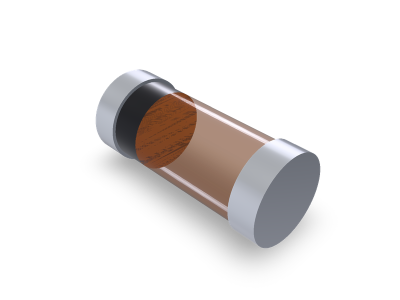
Surface-mount diode packages MELF (DO-213AB), MiniMELF (SOD-80) and MicroMELF, from Vishay's package drawings.
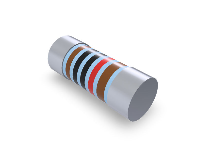
Thin film MELF resistors, Vishay Beyschlag MMU 0102 (MicroMELF), MMA 0204 (MiniMELF) and MMB 0207 (MELF), with colour rings.
| 1 | """Thin film MELF resistor, Vishay Beyschlag MMU 0102 (MicroMELF), MMA 0204 (MiniMELF) or MMB 0207 (MELF). Lying on the XY plane (the board) |
| 2 | with its axis along X and centred on the origin in X and Y: the coated ceramic body between two metal end caps, each end cap its own solid. |
| 3 | The resistance and tolerance make the colour rings on the body (IEC 60062), read from the -X end. Dimensions from Vishay's data sheet, |
| 4 | listed in the README.""" |
| 5 | import math |
| 6 | |
| 7 | from steve import Model |
| 8 | |
| 9 | size = "MMA0204" # MMU0102 (MicroMELF), MMA0204 (MiniMELF) or MMB0207 (MELF) |
| 10 | resistance = 10000.0 # Ω Resistance (in the range the sheet gives for the size and tolerance) |
| 11 | tolerance = "F" # B 0.1 %, C 0.25 %, D 0.5 %, F 1 %, G 2 %, J 5 % (one the sheet offers for this resistance) |
| 12 | |
| 13 | # Vishay Beyschlag "MMU 0102, MMA 0204, MMB 0207 - Thin Film MELF Resistors", document number 28963, revision 02-Jun-2026, page 13, |
| 14 | # table "DIMENSIONS AND MASS", in mm: L, D (end caps), D1 (body) = D + 0 / - x, L1 min. (between the end caps), K (end caps' length), and |
| 15 | # the mass in mg. Each entry: (L (min, max), D (min, max), x, L1 min., K (min, max), mass). |
| 16 | SIZES = { |
| 17 | "MMU0102": ((2.1, 2.2), (1.0, 1.1), 0.1, 1.2, (0.35, 0.5), 8), |
| 18 | "MMA0204": ((3.4, 3.6), (1.3, 1.4), 0.15, 1.8, (0.65, 0.85), 22), |
| 19 | "MMB0207": ((5.65, 5.8), (2.0, 2.2), 0.2, 3.2, (1.05, 1.25), 80), |
| 20 | } |
| 21 | # The same sheet, pages 2 and 3, "TEMPERATURE COEFFICIENT AND RESISTANCE RANGE": the resistance ranges in Ω by tolerance, every temperature |
| 22 | # coefficient's rows taken together (jumpers left out). |
| 23 | RANGES = { |
| 24 | "MMU0102": {"J": ((0.22, 0.91),), "G": ((1, 9.1),), "F": ((10, 2.21e6),), "D": ((10, 221e3),), "C": ((47, 332e3),), |
| 25 | "B": ((100, 221e3),)}, |
| 26 | "MMA0204": {"J": ((0.22, 0.91),), "F": ((0.22, 0.91), (1, 10e6)), "D": ((10, 2.21e6),), "C": ((10, 5.11e6),), "B": ((10, 5.11e6),)}, |
| 27 | "MMB0207": {"J": ((0.1, 0.2), (0.22, 0.91)), "G": ((0.1, 0.2), (0.22, 0.91)), "F": ((0.22, 0.91), (1, 15e6)), "D": ((10, 1e6),), |
| 28 | "C": ((15, 10e6),), "B": ((20, 10e6),)}, |
| 29 | } |
| 30 | # Colour code, IEC 60062 (the sheet, page 5: "Four (E24 series) or five (E96 and E192 series) color code rings designate the resistance value |
| 31 | # and tolerance in accordance with IEC 60062"; page 13: "The last color band for tolerance is approximately 50 % wider than the other |
| 32 | # bands"): ± 5 % and ± 2 % carry two digit rings, the closer tolerances three; then the multiplier ring (pink x 0.001, silver x 0.01, |
| 33 | # gold x 0.1) and the tolerance ring. |
| 34 | DIGIT_COLOURS = ("#1a1a1a", "#7a4a26", "#c8302c", "#e8792b", "#f2d22e", "#3f8f3f", "#2f5fb3", "#7d4fa8", "#8a8a8a", "#f4f4f4") |
| 35 | MULTIPLIER_COLOURS = {-3: "#f0a3b8", -2: "#c0c0c4", -1: "#cfa646", 0: "#1a1a1a", 1: "#7a4a26", 2: "#c8302c", 3: "#e8792b", 4: "#f2d22e", |
| 36 | 5: "#3f8f3f", 6: "#2f5fb3"} |
| 37 | TOLERANCE_COLOURS = {"B": "#7d4fa8", "C": "#2f5fb3", "D": "#3f8f3f", "F": "#7a4a26", "G": "#c8302c", "J": "#cfa646"} |
| 38 | # Proportions, for looks (the sheet shows the rings but doesn't dimension them): each ring is RING of the body's length between the end caps |
| 39 | # wide (the tolerance ring 1.5 times that), with equal gaps between the rings and at their ends. |
| 40 | RING = 0.1 |
| 41 | |
| 42 | if size not in SIZES: |
| 43 | raise ValueError(f"no size {size!r}: {', '.join(SIZES)}") |
| 44 | if tolerance not in RANGES[size]: |
| 45 | raise ValueError(f"Vishay {size} comes in tolerance {', '.join(RANGES[size])}") |
| 46 | if not any(low * (1 - 1e-9) <= resistance <= high * (1 + 1e-9) for low, high in RANGES[size][tolerance]): |
| 47 | spans = " or ".join(f"{low:g} to {high:g} Ω" for low, high in RANGES[size][tolerance]) |
| 48 | raise ValueError(f"Vishay {size} at tolerance {tolerance}: {spans}") |
| 49 | DIGITS = 2 if tolerance in "JG" else 3 |
| 50 | exponent = math.floor(math.log10(resistance) + 1e-9) - (DIGITS - 1) |
| 51 | digits = round(resistance / 10 ** exponent) |
| 52 | if digits >= 10 ** DIGITS: |
| 53 | digits, exponent = digits // 10, exponent + 1 |
| 54 | if not math.isclose(digits * 10.0 ** exponent, resistance, rel_tol=1e-6) or exponent not in MULTIPLIER_COLOURS: |
| 55 | raise ValueError(f"{resistance} Ω can't be written in {DIGITS} digit rings and a multiplier ring") |
| 56 | |
| 57 | |
| 58 | def mid(pair): |
| 59 | return (pair[0] + pair[1]) / 2 |
| 60 | |
| 61 | |
| 62 | LEN, CAP_D, UNDER, _l1, CAP_L, _mass = SIZES[size] |
| 63 | length, cap_d, cap_l = mid(LEN), mid(CAP_D), mid(CAP_L) |
| 64 | body_d = cap_d - UNDER / 2 # D1 is D + 0 / - x: the middle |
| 65 | inside = length / 2 - cap_l |
| 66 | axis_z = cap_d / 2 # the part rests on its end caps |
| 67 | |
| 68 | |
| 69 | def ring_colours(): |
| 70 | text = str(digits).rjust(DIGITS, "0") |
| 71 | return [DIGIT_COLOURS[int(t)] for t in text] + [MULTIPLIER_COLOURS[exponent], TOLERANCE_COLOURS[tolerance]] |
| 72 | |
| 73 | |
| 74 | def body_outline(): |
| 75 | """The body's half section (x, z) from -inside to +inside, with a point at each ring's edges, and the rings' segment indices.""" |
| 76 | span = 2 * inside |
| 77 | widths = [RING * span] * (DIGITS + 1) + [1.5 * RING * span] |
| 78 | gap = (span - sum(widths)) / (len(widths) + 1) |
| 79 | pts = [(-inside, axis_z), (-inside, axis_z + body_d / 2)] |
| 80 | segments = [] |
| 81 | x = -inside + gap |
| 82 | for w in widths: |
| 83 | pts.append((x, axis_z + body_d / 2)) |
| 84 | segments.append(len(pts) - 1) |
| 85 | pts.append((x + w, axis_z + body_d / 2)) |
| 86 | x += w + gap |
| 87 | pts += [(inside, axis_z + body_d / 2), (inside, axis_z)] |
| 88 | return pts, segments |
| 89 | |
| 90 | |
| 91 | model = Model() |
| 92 | # Each cylinder starts at `at` and runs along +X. |
| 93 | for tag, x0 in (("cap_1", -length / 2), ("cap_2", inside)): |
| 94 | model.cylinder(tag, cap_d / 2, cap_l, at=(x0, 0, axis_z), direction=(1, 0, 0), op="new", body=f"{tag}_body", name="End caps") |
| 95 | outline, rings = body_outline() |
| 96 | with model.sketch("body_sketch", on="XZ", name="Body") as sk: |
| 97 | sk.polyline("body_outline", outline, closed=True) |
| 98 | model.revolve("body", "body_sketch", axis=((0, 0, axis_z), (1, 0, 0)), op="new", body="body_body", name="Body") |
| 99 | # Materials, for looks and a rough mass (the sheet, page 5: "a high grade ceramic body (Al2O3)", "Nickel plated steel termination caps", |
| 100 | # "a final pure matte tin on nickel plating"): the body alumina under its protective coating (the coating's colour is for looks only: the |
| 101 | # sheet doesn't name one); the end caps steel, tin plated. |
| 102 | model.material("alumina", bodies=["body_body"], color="#9cc3e0") |
| 103 | model.material("steel-generic", bodies=["cap_1_body", "cap_2_body"], color="#c9ccd1") |
| 104 | for i, colour in zip(rings, ring_colours()): |
| 105 | model.appearance(color=colour, faces=[f"body.side(body_outline.side{i})"]) |
| 106 | result = model.result() |
| 107 |
| 1 | name = "steve/melf-resistor" |
| 2 | version = "1.0.0" |
| 3 | runtime = "steve" |
| 4 | license = "MIT" |
| 5 | summary = "Thin film MELF resistors, Vishay Beyschlag MMU 0102 (MicroMELF), MMA 0204 (MiniMELF) and MMB 0207 (MELF), with colour rings." |
| 6 | description = """Cylindrical surface-mount resistors for board layouts and enclosures: the coated ceramic body between two metal end caps, each end cap its own solid, with the colour rings of the resistance and tolerance. Vishay Beyschlag's thin film MELF resistors in DIN sizes 0102, 0204 and 0207; the size gives the dimensions, from Vishay's data sheet. See the README.""" |
| 7 | tags = ["resistor", "smd", "melf", "minimelf", "micromelf", "thin-film", "vishay", "electronics"] |
| 8 | |
| 9 | [parameters.size] |
| 10 | type = "choice" |
| 11 | default = "MMA0204" |
| 12 | choices = ["MMU0102", "MMA0204", "MMB0207"] |
| 13 | label = "Size" |
| 14 | description = "MMU0102: MicroMELF, 2.2 x Ø 1.1. MMA0204: MiniMELF, 3.6 x Ø 1.4. MMB0207: MELF, 5.8 x Ø 2.2 (largest sizes)." |
| 15 | |
| 16 | [parameters.resistance] |
| 17 | type = "number" |
| 18 | default = 10000.0 |
| 19 | min = 0.1 |
| 20 | max = 15000000 |
| 21 | unit = "Ω" |
| 22 | label = "Resistance" |
| 23 | description = "In the range the sheet gives for the size and tolerance; it sets the colour rings." |
| 24 | |
| 25 | [parameters.tolerance] |
| 26 | type = "choice" |
| 27 | default = "F" |
| 28 | choices = ["B", "C", "D", "F", "G", "J"] |
| 29 | label = "Tolerance" |
| 30 | description = "B 0.1 %, C 0.25 %, D 0.5 %, F 1 % (five rings), G 2 %, J 5 % (four rings). One the sheet offers for this size and resistance." |
| 31 | |
| 32 | [[presets]] |
| 33 | id = "MMU0102" |
| 34 | title = "MicroMELF thin film resistor, Vishay MMU 0102, 10 kΩ 1 %" |
| 35 | params = { size = "MMU0102", resistance = 10000, tolerance = "F" } |
| 36 | aliases = ["MMU 0102", "Vishay MMU 0102", "MicroMELF resistor 0102", "MMU0102"] |
| 37 | standard = "Vishay MMU 0102" |
| 38 | |
| 39 | [[presets]] |
| 40 | id = "MMA0204" |
| 41 | title = "MiniMELF thin film resistor, Vishay MMA 0204, 10 kΩ 1 %" |
| 42 | params = { size = "MMA0204", resistance = 10000, tolerance = "F" } |
| 43 | aliases = ["MMA 0204", "Vishay MMA 0204", "MiniMELF resistor 0204", "MMA0204"] |
| 44 | standard = "Vishay MMA 0204" |
| 45 | |
| 46 | [[presets]] |
| 47 | id = "MMB0207" |
| 48 | title = "MELF thin film resistor, Vishay MMB 0207, 10 kΩ 1 %" |
| 49 | params = { size = "MMB0207", resistance = 10000, tolerance = "F" } |
| 50 | aliases = ["MMB 0207", "Vishay MMB 0207", "MELF resistor 0207", "MMB0207"] |
| 51 | standard = "Vishay MMB 0207" |
| 52 |
Vishay Beyschlag's thin film MELF resistors: MMU 0102 (MicroMELF), MMA 0204 (MiniMELF) and MMB 0207 (MELF). The resistor lies on the XY plane (the board) with its axis along X, centred on the origin in X and Y. It is the coated ceramic body between two metal end caps, and each end cap is its own solid. The resistance and tolerance set the colour rings on the body (IEC 60062), read from the -X end.
size: MMU0102, MMA0204 or MMB0207.resistance in Ω, and tolerance: B 0.1 %, C 0.25 %, D 0.5 %, F 1 %, G 2 % or J 5 %. Only the combinations the sheet lists are accepted (table below). ± 5 % and ± 2 % carry two digit rings, and the closer tolerances three. Then come the multiplier ring and the tolerance ring.Vishay Beyschlag, "MMU 0102, MMA 0204, MMB 0207 - Thin Film MELF Resistors", document number 28963, revision 02-Jun-2026, https://www.vishay.com/doc?28963.
Page 13, "DIMENSIONS AND MASS" (mm):
| Size | L | D (end caps) | D1 (body) | L1 min. | K (end cap length) | Mass |
|---|---|---|---|---|---|---|
| MMU 0102 | 2.2 + 0 / - 0.1 | 1.1 + 0 / - 0.1 | D + 0 / - 0.1 | 1.2 | 0.4 + 0.1 / - 0.05 | 8 mg |
| MMA 0204 | 3.6 + 0 / - 0.2 | 1.4 + 0 / - 0.1 | D + 0 / - 0.15 | 1.8 | 0.75 ± 0.1 | 22 mg |
| MMB 0207 | 5.8 + 0 / - 0.15 | 2.2 + 0 / - 0.2 | D + 0 / - 0.2 | 3.2 | 1.15 ± 0.1 | 80 mg |
The model uses the middle of each range. The body between the end caps is L - 2K long, which is more than L1 min. for every size.
Pages 2 and 3, "TEMPERATURE COEFFICIENT AND RESISTANCE RANGE": the resistance ranges by tolerance, every temperature coefficient's rows taken together. Jumpers aren't offered.
| Size | B 0.1 % | C 0.25 % | D 0.5 % | F 1 % | G 2 % | J 5 % |
|---|---|---|---|---|---|---|
| MMU 0102 | 100 Ω to 221 kΩ | 47 Ω to 332 kΩ | 10 Ω to 221 kΩ | 10 Ω to 2.21 MΩ | 1 Ω to 9.1 Ω | 0.22 Ω to 0.91 Ω |
| MMA 0204 | 10 Ω to 5.11 MΩ | 10 Ω to 5.11 MΩ | 10 Ω to 2.21 MΩ | 0.22 Ω to 0.91 Ω, 1 Ω to 10 MΩ | – | 0.22 Ω to 0.91 Ω |
| MMB 0207 | 20 Ω to 10 MΩ | 15 Ω to 10 MΩ | 10 Ω to 1 MΩ | 0.22 Ω to 0.91 Ω, 1 Ω to 15 MΩ | 0.1 Ω to 0.2 Ω, 0.22 Ω to 0.91 Ω | 0.1 Ω to 0.2 Ω, 0.22 Ω to 0.91 Ω |
Page 5: "Four (E24 series) or five (E96 and E192 series) color code rings designate the resistance value and tolerance in accordance with IEC 60062". Page 13: "The last color band for tolerance is approximately 50 % wider than the other bands."
Proportions, stated plainly. The sheet shows the rings but doesn't dimension them. Each ring is 0.1 of the body's length between the end caps wide, and the tolerance ring is 1.5 times that. The gaps between the rings and at their ends are equal. The rings are flush with the body.
Materials and mass. Page 5 says "a high grade ceramic body (Al2O3)", "Nickel plated steel termination caps" and "a final pure matte tin on nickel plating". The body is alumina and the end caps are steel. The sheet doesn't name the coating's colour; the light blue is for looks only. The model weighs about 10 mg (MMU 0102), 27 mg (MMA 0204) and 105 mg (MMB 0207), against the sheet's 8, 22 and 80 mg. It is heavier because the end caps are modelled solid steel, where the real caps are pressed over the ceramic rod's ends.
The old catalogue's R_MicroMELF_MMU-0102, R_MiniMELF_MMA-0204 and R_MELF_MMB-0207 entries have no models to measure. Each names the Vishay series and size, and each maps to it. Each preset is 10 kΩ at 1 %.
The family is shared with chip-resistor. The other resistors in it (arrays, shunts and the chip sizes Vishay's D/CRCW e3 doesn't have) aren't read here; see COVERAGE.md.
| 1 | # MELF resistor |
| 2 | |
| 3 | Vishay Beyschlag's thin film MELF resistors: MMU 0102 (MicroMELF), MMA 0204 (MiniMELF) and MMB 0207 (MELF). The resistor lies on the XY plane (the board) with its axis along X, centred on the origin in X and Y. It is the coated ceramic body between two metal end caps, and each end cap is its own solid. The resistance and tolerance set the colour rings on the body (IEC 60062), read from the -X end. |
| 4 | |
| 5 | ## Parameters |
| 6 | |
| 7 | - `size`: `MMU0102`, `MMA0204` or `MMB0207`. |
| 8 | - `resistance` in Ω, and `tolerance`: B 0.1 %, C 0.25 %, D 0.5 %, F 1 %, G 2 % or J 5 %. Only the combinations the sheet lists are accepted (table below). ± 5 % and ± 2 % carry two digit rings, and the closer tolerances three. Then come the multiplier ring and the tolerance ring. |
| 9 | |
| 10 | ## Source |
| 11 | |
| 12 | Vishay Beyschlag, "MMU 0102, MMA 0204, MMB 0207 - Thin Film MELF Resistors", document number 28963, revision 02-Jun-2026, <https://www.vishay.com/doc?28963>. |
| 13 | |
| 14 | Page 13, "DIMENSIONS AND MASS" (mm): |
| 15 | |
| 16 | | Size | L | D (end caps) | D1 (body) | L1 min. | K (end cap length) | Mass | |
| 17 | |---|---|---|---|---|---|---| |
| 18 | | MMU 0102 | 2.2 + 0 / - 0.1 | 1.1 + 0 / - 0.1 | D + 0 / - 0.1 | 1.2 | 0.4 + 0.1 / - 0.05 | 8 mg | |
| 19 | | MMA 0204 | 3.6 + 0 / - 0.2 | 1.4 + 0 / - 0.1 | D + 0 / - 0.15 | 1.8 | 0.75 ± 0.1 | 22 mg | |
| 20 | | MMB 0207 | 5.8 + 0 / - 0.15 | 2.2 + 0 / - 0.2 | D + 0 / - 0.2 | 3.2 | 1.15 ± 0.1 | 80 mg | |
| 21 | |
| 22 | The model uses the middle of each range. The body between the end caps is L - 2K long, which is more than L1 min. for every size. |
| 23 | |
| 24 | Pages 2 and 3, "TEMPERATURE COEFFICIENT AND RESISTANCE RANGE": the resistance ranges by tolerance, every temperature coefficient's rows taken together. Jumpers aren't offered. |
| 25 | |
| 26 | | Size | B 0.1 % | C 0.25 % | D 0.5 % | F 1 % | G 2 % | J 5 % | |
| 27 | |---|---|---|---|---|---|---| |
| 28 | | MMU 0102 | 100 Ω to 221 kΩ | 47 Ω to 332 kΩ | 10 Ω to 221 kΩ | 10 Ω to 2.21 MΩ | 1 Ω to 9.1 Ω | 0.22 Ω to 0.91 Ω | |
| 29 | | MMA 0204 | 10 Ω to 5.11 MΩ | 10 Ω to 5.11 MΩ | 10 Ω to 2.21 MΩ | 0.22 Ω to 0.91 Ω, 1 Ω to 10 MΩ | – | 0.22 Ω to 0.91 Ω | |
| 30 | | MMB 0207 | 20 Ω to 10 MΩ | 15 Ω to 10 MΩ | 10 Ω to 1 MΩ | 0.22 Ω to 0.91 Ω, 1 Ω to 15 MΩ | 0.1 Ω to 0.2 Ω, 0.22 Ω to 0.91 Ω | 0.1 Ω to 0.2 Ω, 0.22 Ω to 0.91 Ω | |
| 31 | |
| 32 | Page 5: "Four (E24 series) or five (E96 and E192 series) color code rings designate the resistance value and tolerance in accordance with IEC 60062". Page 13: "The last color band for tolerance is approximately 50 % wider than the other bands." |
| 33 | |
| 34 | **Proportions, stated plainly.** The sheet shows the rings but doesn't dimension them. Each ring is 0.1 of the body's length between the end caps wide, and the tolerance ring is 1.5 times that. The gaps between the rings and at their ends are equal. The rings are flush with the body. |
| 35 | |
| 36 | **Materials and mass.** Page 5 says "a high grade ceramic body (Al2O3)", "Nickel plated steel termination caps" and "a final pure matte tin on nickel plating". The body is alumina and the end caps are steel. The sheet doesn't name the coating's colour; the light blue is for looks only. The model weighs about 10 mg (MMU 0102), 27 mg (MMA 0204) and 105 mg (MMB 0207), against the sheet's 8, 22 and 80 mg. It is heavier because the end caps are modelled solid steel, where the real caps are pressed over the ceramic rod's ends. |
| 37 | |
| 38 | ## Catalogue models |
| 39 | |
| 40 | The old catalogue's `R_MicroMELF_MMU-0102`, `R_MiniMELF_MMA-0204` and `R_MELF_MMB-0207` entries have no models to measure. Each names the Vishay series and size, and each maps to it. Each preset is 10 kΩ at 1 %. |
| 41 | |
| 42 | The family is shared with `chip-resistor`. The other resistors in it (arrays, shunts and the chip sizes Vishay's D/CRCW e3 doesn't have) aren't read here; see `COVERAGE.md`. |
| 43 |
Cylindrical surface-mount resistors for board layouts and enclosures: the coated ceramic body between two metal end caps, each end cap its own solid, with the colour rings of the resistance and tolerance. Vishay Beyschlag's thin film MELF resistors in DIN sizes 0102, 0204 and 0207; the size gives the dimensions, from Vishay's data sheet. See the README.
Vishay Beyschlag's thin film MELF resistors: MMU 0102 (MicroMELF), MMA 0204 (MiniMELF) and MMB 0207 (MELF). The resistor lies on the XY plane (the board) with its axis along X, centred on the origin in X and Y. It is the coated ceramic body between two metal end caps, and each end cap is its own solid. The resistance and tolerance set the colour rings on the body (IEC 60062), read from the -X end.
size: MMU0102, MMA0204 or MMB0207.resistance in Ω, and tolerance: B 0.1 %, C 0.25 %, D 0.5 %, F 1 %, G 2 % or J 5 %. Only the combinations the sheet lists are accepted (table below). ± 5 % and ± 2 % carry two digit rings, and the closer tolerances three. Then come the multiplier ring and the tolerance ring.Vishay Beyschlag, "MMU 0102, MMA 0204, MMB 0207 - Thin Film MELF Resistors", document number 28963, revision 02-Jun-2026, https://www.vishay.com/doc?28963.
Page 13, "DIMENSIONS AND MASS" (mm):
| Size | L | D (end caps) | D1 (body) | L1 min. | K (end cap length) | Mass |
|---|---|---|---|---|---|---|
| MMU 0102 | 2.2 + 0 / - 0.1 | 1.1 + 0 / - 0.1 | D + 0 / - 0.1 | 1.2 | 0.4 + 0.1 / - 0.05 | 8 mg |
| MMA 0204 | 3.6 + 0 / - 0.2 | 1.4 + 0 / - 0.1 | D + 0 / - 0.15 | 1.8 | 0.75 ± 0.1 | 22 mg |
| MMB 0207 | 5.8 + 0 / - 0.15 | 2.2 + 0 / - 0.2 | D + 0 / - 0.2 | 3.2 | 1.15 ± 0.1 | 80 mg |
The model uses the middle of each range. The body between the end caps is L - 2K long, which is more than L1 min. for every size.
Pages 2 and 3, "TEMPERATURE COEFFICIENT AND RESISTANCE RANGE": the resistance ranges by tolerance, every temperature coefficient's rows taken together. Jumpers aren't offered.
| Size | B 0.1 % | C 0.25 % | D 0.5 % | F 1 % | G 2 % | J 5 % |
|---|---|---|---|---|---|---|
| MMU 0102 | 100 Ω to 221 kΩ | 47 Ω to 332 kΩ | 10 Ω to 221 kΩ | 10 Ω to 2.21 MΩ | 1 Ω to 9.1 Ω | 0.22 Ω to 0.91 Ω |
| MMA 0204 | 10 Ω to 5.11 MΩ | 10 Ω to 5.11 MΩ | 10 Ω to 2.21 MΩ | 0.22 Ω to 0.91 Ω, 1 Ω to 10 MΩ | – | 0.22 Ω to 0.91 Ω |
| MMB 0207 | 20 Ω to 10 MΩ | 15 Ω to 10 MΩ | 10 Ω to 1 MΩ | 0.22 Ω to 0.91 Ω, 1 Ω to 15 MΩ | 0.1 Ω to 0.2 Ω, 0.22 Ω to 0.91 Ω | 0.1 Ω to 0.2 Ω, 0.22 Ω to 0.91 Ω |
Page 5: "Four (E24 series) or five (E96 and E192 series) color code rings designate the resistance value and tolerance in accordance with IEC 60062". Page 13: "The last color band for tolerance is approximately 50 % wider than the other bands."
Proportions, stated plainly. The sheet shows the rings but doesn't dimension them. Each ring is 0.1 of the body's length between the end caps wide, and the tolerance ring is 1.5 times that. The gaps between the rings and at their ends are equal. The rings are flush with the body.
Materials and mass. Page 5 says "a high grade ceramic body (Al2O3)", "Nickel plated steel termination caps" and "a final pure matte tin on nickel plating". The body is alumina and the end caps are steel. The sheet doesn't name the coating's colour; the light blue is for looks only. The model weighs about 10 mg (MMU 0102), 27 mg (MMA 0204) and 105 mg (MMB 0207), against the sheet's 8, 22 and 80 mg. It is heavier because the end caps are modelled solid steel, where the real caps are pressed over the ceramic rod's ends.
The old catalogue's R_MicroMELF_MMU-0102, R_MiniMELF_MMA-0204 and R_MELF_MMB-0207 entries have no models to measure. Each names the Vishay series and size, and each maps to it. Each preset is 10 kΩ at 1 %.
The family is shared with chip-resistor. The other resistors in it (arrays, shunts and the chip sizes Vishay's D/CRCW e3 doesn't have) aren't read here; see COVERAGE.md.
Surface-mount diode packages MELF (DO-213AB), MiniMELF (SOD-80) and MicroMELF, from Vishay's package drawings.
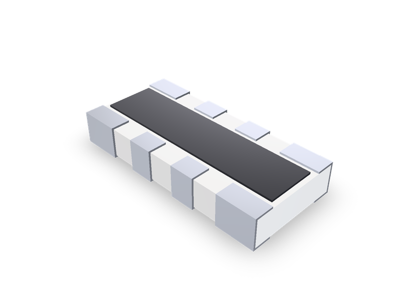
Thick film chip resistor arrays with convex terminals, Vishay CRA04S (0402), CRA06E/S (0603) and CRA12E/S (1206), 4 to 10 terminals.
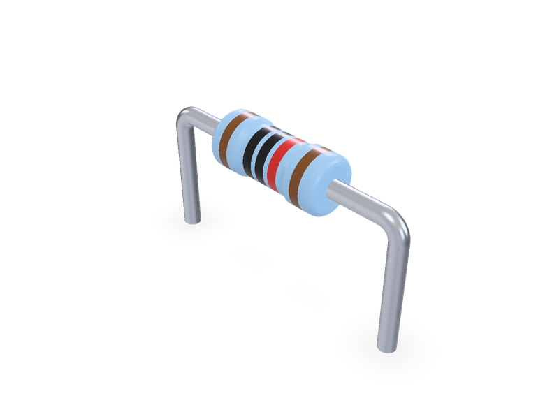
Axial leaded metal film resistor, Vishay Beyschlag MBA/SMA 0204, MBB/SMA 0207 and MBE/SMA 0414, with colour rings, horizontal or vertical.
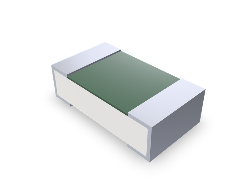
Thin film chip fuses, Vishay MFU series, 0402, 0603, 0805 and 1206.