
STEVEMIT
steve/radial-inductor
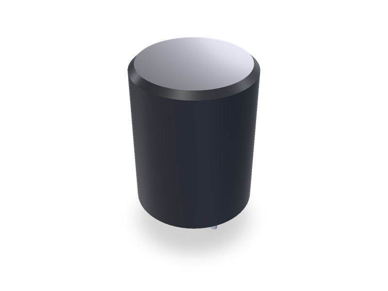
Radial leaded inductor, Fastron pin type coils: 07M shielded, 07P and 11P with tube, 07HCP, 09HCP and 07HVP open or with tube.
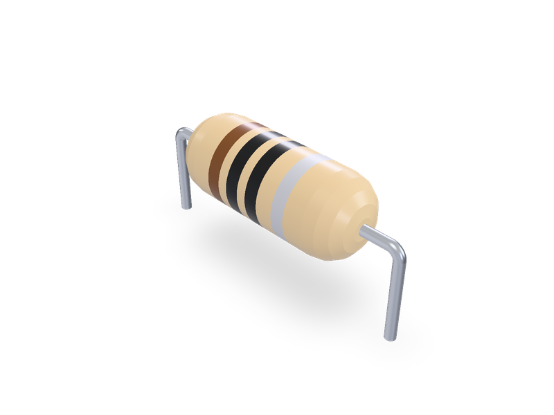
Axial leaded inductor, Fastron fixed choke coils (MICC, SMCC, MECC, HCCC, LACC, HBCC, VHBCC, XHBCC) and suppression coils (MISC, MESC, 77A), Vishay Dale molded IM-1 to IM-10, horizontal or vertical.
| 1 | """Leaded (axial) inductor, Fastron fixed choke coils (MICC, SMCC, MECC, HCCC, LACC, HBCC, VHBCC, XHBCC) and suppression coils (MISC, MESC, |
| 2 | 77A), and Vishay Dale's molded IM-1 to IM-10, mounted horizontal or vertical. Lead 1 is at the origin and lead 2 at +X by the pitch; the leads go down through the board. |
| 3 | Horizontal: the body lies on the board along X, centred between the leads. Vertical: the body stands on the board over lead 1 and lead 2 |
| 4 | comes back down beside it. The series, inductance and tolerance make the part number (e.g. MECC-100K); the size follows from them. |
| 5 | Dimensions from Fastron's and Vishay's data sheets, listed in the README.""" |
| 6 | import math |
| 7 | |
| 8 | from steve import Model |
| 9 | |
| 10 | series = "MECC" # Series |
| 11 | inductance = 10.0 # µH Inductance (one the series' data sheet lists) |
| 12 | tolerance = "K" # J 5 %, K 10 %, M 20 % (the colour bands; one the sheet offers for this inductance) |
| 13 | mounting = "horizontal" # horizontal or vertical |
| 14 | pitch = 15.24 # mm Lead pitch on the board |
| 15 | tail = 3.0 # mm Leads below the board |
| 16 | detail = "full" # full: body, colour bands and leads; simple: the body only |
| 17 | |
| 18 | # Body sizes (length max, diameter max, lead diameter) in mm by series and inductance in µH, from Fastron's data sheets, each one page |
| 19 | # (fastrongroup.com, product pages of the series; "Revision date" printed on each sheet): |
| 20 | # MICC (08 Feb 2021): 7 max, Ø 3.3 max for R10 to 150 and Ø 3.0 max for 180 to 102, lead Ø 0.5. |
| 21 | # SMCC (05 Aug 2021): 9.5 max, Ø 4.0 max, lead Ø 0.60. MECC (06 Jul 2017): 11.0 max, Ø 4.5 max, lead Ø 0.6. |
| 22 | # HCCC (11 Aug 2014): 13 max, Ø 4.5 max, lead Ø 0.8. LACC (11 Aug 2014): 14.0 max, Ø 4.5 max, lead Ø 0.6. |
| 23 | # HBCC (14 Apr 2025): A 14.5 max for 1.0 to 18 µH, 12.8 max for 22 to 100000 µH, Ø 5.8 max, lead Ø 0.60. |
| 24 | # VHBCC (23 May 2017): 16.0 max, Ø D 6.3 max for 47 µH and 6.0 for 10 to 33 and 68 to 100000 µH, lead Ø 0.7. |
| 25 | # XHBCC (31 May 2016): 16 max, Ø 7.5 max, lead Ø 0.7. |
| 26 | # MISC (27 Apr 2017): 12.0 max overall, 10.0 max winding, Ø 5.0 max, lead Ø 0.80. MESC (13 Oct 2017): 24.0 max, Ø 7.5 max, lead Ø 0.80. |
| 27 | # 77A (26 Jun 2025): dimension table A max, Ø D max, Ø d by part number, 3 ref at each end (Fig 1 and 2). |
| 28 | # Each entry: (inductances in µH, length, diameter, lead diameter). |
| 29 | SIZES = { |
| 30 | "MICC": (((0.1, 150), 7.0, 3.3, 0.5), ((180, 1000), 7.0, 3.0, 0.5)), |
| 31 | "SMCC": (((0.1, 10000), 9.5, 4.0, 0.6),), |
| 32 | "MECC": (((1, 150), 11.0, 4.5, 0.6),), |
| 33 | "HCCC": (((0.7, 33), 13.0, 4.5, 0.8),), |
| 34 | "LACC": (((1, 56), 14.0, 4.5, 0.6),), |
| 35 | "HBCC": (((1, 18), 14.5, 5.8, 0.6), ((22, 100000), 12.8, 5.8, 0.6)), |
| 36 | "VHBCC": (((47, 47), 16.0, 6.3, 0.7), ((10, 33), 16.0, 6.0, 0.7), ((68, 100000), 16.0, 6.0, 0.7)), |
| 37 | "XHBCC": (((100, 100000), 16.0, 7.5, 0.7),), |
| 38 | "MISC": (((1, 100), 12.0, 5.0, 0.8),), |
| 39 | "MESC": (((3, 1500), 24.0, 7.5, 0.8),), |
| 40 | "77A": (((3.9, 3.9), 30.0, 8.0, 1.0), ((5.6, 10), 26.0, 8.0, 0.8), ((15, 15), 26.0, 9.0, 0.8), ((33, 33), 26.0, 10.0, 0.8), ((40, 10000), 26.0, 11.0, 0.8)), |
| 41 | # Vishay Dale IM, "Inductors, Commercial, Molded, Axial Leaded", document 34030, revision 28-Aug-13, DIMENSIONS table (inches [mm]): the |
| 42 | # maximum of A (diameter), B (length) and D (lead diameter). |
| 43 | "IM-1": (((0.1, 100), 5.33, 2.18, 0.546),), |
| 44 | "IM-2": (((0.022, 1000), 6.60, 2.67, 0.546),), |
| 45 | "IM-4": (((0.15, 1800), 9.78, 4.19, 0.686),), |
| 46 | "IM-6": (((0.1, 1000), 11.43, 5.08, 0.686),), |
| 47 | "IM-8": (((1100, 3600), 14.48, 5.72, 0.762),), |
| 48 | "IM-9": (((68, 150), 14.48, 6.60, 0.686),), |
| 49 | "IM-10": (((3900, 10000), 19.05, 6.35, 0.864),), |
| 50 | } |
| 51 | # The inductances each sheet lists (µH), by the tolerances it offers for them (J 5 %, K 10 %, M 20 %): the part number table of each sheet. |
| 52 | VALUES = { |
| 53 | "MICC": {"KM": (0.1, 0.11, 0.12, 0.15, 0.18, 0.2, 0.22, 0.27, 0.33, 0.39, 0.47, 0.56, 0.68, 0.82), |
| 54 | "JKM": (1, 1.2, 1.3, 1.5, 1.8, 2.2, 2.4, 2.7, 3.3, 3.9, 4, 4.4, 4.7, 4.9, 5, 5.6, 6.2, 6.8, 8.2, 10, 12, 15, 18, 22, 27, 33, 39, 47, 56, 62, 68, 82, |
| 55 | 100, 120, 150, 180, 220, 270, 280, 330, 350, 390, 470, 560, 680, 820, 1000)}, |
| 56 | "SMCC": {"KM": (0.1, 0.12, 0.15, 0.18, 0.22, 0.27, 0.33, 0.39, 0.47, 0.56, 0.68, 0.82), |
| 57 | "JKM": (1, 1.2, 1.5, 1.8, 2.2, 2.7, 3.3, 3.9, 4.7, 5.6, 6.2, 6.8, 8.2, 10, 12, 15, 18, 20, 22, 27, 30, 33, 39, 47, 56, 68, 82, 100, 120, 150, 160, |
| 58 | 180, 200, 220, 270, 330, 350, 390, 470, 560, 680, 820, 1000, 1200, 1500, 1800, 2200, 2700, 3300, 3500, 3900, 4700, 5000, 5600, 6800, |
| 59 | 8100, 8200, 10000)}, |
| 60 | "MECC": {"KM": (1, 1.2, 1.5, 1.8, 2.2, 2.7, 3.3, 3.9, 4.7, 5.6, 6.8, 8.2, 10, 12, 15, 18, 22, 27, 33, 39, 47, 56, 68, 82, 100, 120, 150)}, |
| 61 | "HCCC": {"M": (0.7,), "KM": (1, 1.2, 1.5, 1.8, 2.2, 2.7, 3.3, 3.6, 3.9, 5.6, 6.8, 8.2, 10, 12, 15, 18, 22, 27, 33)}, |
| 62 | "LACC": {"KM": (1, 1.2, 1.5, 1.8, 2.2, 2.7, 3.3, 3.9, 4.7, 5.6, 6.8, 8.2, 10, 12, 15, 18, 22, 24, 27, 33, 39, 43, 47, 56)}, |
| 63 | "HBCC": {"JK": (1, 1.2, 1.5, 1.8, 2.2, 2.7, 3.3, 3.9, 4.7, 5.6, 6.8, 8.2, 10, 12, 15, 18, 22, 25, 27, 33, 39, 47, 56, 68, 82, 100, 120, 150, 180, 220, |
| 64 | 270, 330, 390, 470, 560, 680, 820, 1000, 1200, 1500, 1800, 2200, 2700, 3300, 3900, 4700, 5000, 5300, 6800, 10000, 15000, 18000, |
| 65 | 22000, 33000, 36000, 39000, 47000, 68000, 100000)}, |
| 66 | "VHBCC": {"JK": (10, 15, 22, 33, 47, 68, 100, 150, 180, 220, 330, 390, 470, 560, 680, 820, 1000, 1200, 1500, 1800, 2200, 2700, 3300, 3900, 4700, |
| 67 | 5600, 6800, 8200, 10000, 12000, 15000, 18000, 22000, 27000, 33000, 47000, 68000, 100000)}, |
| 68 | "XHBCC": {"K": (100, 150, 220, 330, 470), |
| 69 | "JK": (680, 1000, 1500, 1700, 2000, 2200, 2400, 2500, 2700, 3000, 3300, 3500, 3600, 4500, 4700, 5300, 6800, 10000, 15000, 22000, 33000, |
| 70 | 47000, 68000, 100000)}, |
| 71 | "MISC": {"M": (1, 2, 3, 6, 14, 30, 40, 100)}, |
| 72 | "MESC": {"M": (3, 3.3, 5, 7, 10, 12, 15, 22, 25, 40, 55, 56, 75, 100, 130, 160, 220, 330, 350, 470, 680, 1200, 1500)}, |
| 73 | "77A": {"M": (3.9, 5.6, 10, 15, 33, 40, 68, 80, 100, 120, 150, 330, 470, 500, 680, 820, 1000, 1500, 3300, 4700, 5600, 6800, 10000)}, |
| 74 | # Vishay IM, the same document's tables by model; its tolerances are ± 1, 3, 5, 10 and 20 % ("other tolerances available on request"). |
| 75 | "IM-1": {"JKM": (0.1, 0.12, 0.15, 0.18, 0.22, 0.27, 0.33, 0.39, 0.47, 0.56, 0.68, 0.82, 1, 1.2, 1.5, 1.8, 2.2, 2.7, 3.3, 3.9, 4.7, 5.6, 6.8, 8.2, 10, 12, |
| 76 | 15, 18, 22, 27, 33, 39, 47, 56, 68, 82, 100)}, |
| 77 | "IM-2": {"JKM": (0.022, 0.027, 0.033, 0.039, 0.047, 0.056, 0.068, 0.082, 0.1, 0.12, 0.15, 0.18, 0.22, 0.27, 0.33, 0.39, 0.47, 0.56, 0.68, 0.82, 1, 1.2, |
| 78 | 1.5, 1.8, 2.2, 2.7, 3.3, 3.9, 4.7, 5.6, 6.8, 8.2, 10, 12, 15, 18, 22, 27, 33, 39, 47, 56, 68, 82, 100, 120, 150, 180, 220, 270, 330, |
| 79 | 390, 470, 560, 680, 820, 1000)}, |
| 80 | "IM-4": {"JKM": (0.15, 0.22, 0.33, 0.47, 0.56, 0.68, 0.82, 1, 1.2, 1.5, 1.8, 2.2, 2.7, 3.3, 3.9, 4.7, 5.6, 6.8, 8.2, 10, 12, 15, 18, 22, 27, 33, 36, 39, |
| 81 | 43, 47, 51, 56, 62, 68, 75, 82, 91, 100, 110, 120, 130, 150, 160, 180, 200, 220, 240, 270, 300, 330, 360, 390, 430, 470, 510, 560, 620, |
| 82 | 680, 750, 820, 910, 1000, 1100, 1200, 1300, 1500, 1600, 1800)}, |
| 83 | "IM-6": {"JKM": (0.1, 0.12, 0.15, 0.18, 0.22, 0.27, 0.33, 0.39, 0.47, 0.56, 0.68, 0.82, 1, 1.2, 1.5, 1.8, 2.2, 2.7, 3.3, 3.9, 4.7, 5.6, 6.8, 8.2, 10, 12, |
| 84 | 15, 18, 22, 27, 33, 39, 47, 56, 68, 82, 100, 120, 150, 180, 220, 270, 300, 330, 360, 390, 430, 470, 510, 560, 620, 680, 750, 820, 910, |
| 85 | 1000)}, |
| 86 | "IM-8": {"JKM": (1100, 1200, 1300, 1500, 1600, 1800, 2000, 2200, 2400, 2700, 3000, 3300, 3600)}, |
| 87 | "IM-9": {"JKM": (68, 82, 100, 120, 150)}, |
| 88 | "IM-10": {"JKM": (3900, 4300, 4700, 5000, 5600, 6200, 6800, 7500, 8200, 9100, 10000)}, |
| 89 | } |
| 90 | # Suppression coils: a winding seen through a clear insulation foil, no colour bands. The foil's end length at each end: MISC (12.0 - 10.0) / 2 |
| 91 | # from its sheet, 77A "3 ref" from its sheet. MESC's sheet doesn't dimension it: 3 is taken from 77A, the same maker's drawing style, for looks. |
| 92 | SLEEVE_ENDS = {"MISC": 1.0, "MESC": 3.0, "77A": 3.0} |
| 93 | # Colour code (IEC 60062) as the Fastron sheets give it: two digit bands, a multiplier band, a tolerance band (none for M, 20 %). |
| 94 | DIGIT_COLOURS = ("#1a1a1a", "#7a4a26", "#c8302c", "#e8792b", "#f2d22e", "#3f8f3f", "#2f5fb3", "#7d4fa8", "#8a8a8a", "#f4f4f4") |
| 95 | MULTIPLIER_COLOURS = {-2: "#c0c0c4", -1: "#cfa646", 0: "#1a1a1a", 1: "#7a4a26", 2: "#c8302c", 3: "#e8792b", 4: "#f2d22e"} |
| 96 | TOLERANCE_COLOURS = {"J": "#cfa646", "K": "#c0c0c4"} |
| 97 | |
| 98 | if series not in SIZES: |
| 99 | raise ValueError(f"no series {series!r}: {', '.join(SIZES)}") |
| 100 | offered = [(tols, v) for tols, values in VALUES[series].items() for v in values if math.isclose(v, inductance, rel_tol=1e-6)] |
| 101 | if not offered: |
| 102 | raise ValueError(f"Fastron {series} has no {inductance} µH part: see the series' data sheet") |
| 103 | if tolerance not in offered[0][0]: |
| 104 | raise ValueError(f"Fastron {series} {inductance} µH comes in tolerance {' or '.join(offered[0][0])}") |
| 105 | size = [s for s in SIZES[series] if s[0][0] - 1e-9 <= inductance <= s[0][1] + 1e-9] |
| 106 | _range, length, diameter, lead = size[0] |
| 107 | if mounting not in ("horizontal", "vertical"): |
| 108 | raise ValueError("mounting is horizontal or vertical") |
| 109 | R, r = diameter / 2, lead / 2 |
| 110 | BEND = lead # bend radius of the formed leads, one lead diameter: a proportion, for looks (the sheets give none) |
| 111 | LOOP = 2.0 # vertical: lead 2 clears the body's top end by this before it turns down, a proportion |
| 112 | if mounting == "horizontal" and pitch < length + 2 * BEND: |
| 113 | raise ValueError(f"horizontal pitch must leave room to bend the leads: at least {length + 2 * BEND:.2f} mm for a {length} mm body") |
| 114 | if mounting == "vertical" and pitch < max(R + r, 2 * BEND): |
| 115 | raise ValueError(f"vertical pitch must let lead 2 pass the body: at least {max(R + r, 2 * BEND):.2f} mm for a {diameter} mm body") |
| 116 | sleeved = series in SLEEVE_ENDS |
| 117 | molded = series.startswith("IM-") |
| 118 | reach = SLEEVE_ENDS.get(series, 0.0) if detail == "full" else 0.0 # the leads reach into the body this far: to the winding under the foil |
| 119 | |
| 120 | |
| 121 | def body_profile(): |
| 122 | """The body outline as (u along the axis from the body's lead-1 end, radius), and the band segments' indices.""" |
| 123 | if sleeved: |
| 124 | # The foil closes over the winding's ends down to the lead: a quarter-sine curve over the end length, for looks. |
| 125 | end = SLEEVE_ENDS[series] |
| 126 | ends = [(end * (1 - math.cos(math.pi / 2 * i / 4)), r + (R - r) * math.sin(math.pi / 2 * i / 4)) for i in range(1, 5)] |
| 127 | return [(0, 0), (0, r)] + ends + [(length - u, v) for u, v in reversed(ends)] + [(length, r), (length, 0)], [] |
| 128 | if molded: |
| 129 | # Vishay IM: a molded cylinder, its end edges rounded off by 0.15 x the radius, for looks. The sheet's photo shows colour bands but |
| 130 | # the sheet gives no marking code, so none are drawn. |
| 131 | e = 0.15 * R |
| 132 | return [(0, 0), (0, R - e), (e, R), (length - e, R), (length, R - e), (length, 0)], [] |
| 133 | # Coated chokes: tapered ends from the lead out to the full diameter over 0.8 x the radius, for looks; the sheets draw the taper but don't |
| 134 | # dimension it. Four bands, each 0.07 x the length wide, centred at 0.30, 0.42, 0.54 and 0.70 of the length: proportions, for looks. |
| 135 | taper, neck = 0.8 * R, min(lead, 0.6 * R) |
| 136 | pts = [(0, 0), (0, neck)] |
| 137 | pts += [(taper * (1 - math.cos(math.pi / 2 * i / 4)), neck + (R - neck) * math.sin(math.pi / 2 * i / 4)) for i in range(1, 5)] |
| 138 | bands = [] |
| 139 | for centre in (0.30, 0.42, 0.54, 0.70): |
| 140 | a, b = centre * length - 0.035 * length, centre * length + 0.035 * length |
| 141 | pts += [(a, R), (b, R)] |
| 142 | bands.append(len(pts) - 2) |
| 143 | pts += [(length - u, v) for u, v in reversed(pts[2:6])] |
| 144 | pts += [(length, neck), (length, 0)] |
| 145 | return pts, bands |
| 146 | |
| 147 | |
| 148 | def band_colours(): |
| 149 | exponent = math.floor(math.log10(inductance)) - 1 |
| 150 | digits = round(inductance / 10 ** exponent) |
| 151 | if digits >= 100: |
| 152 | digits, exponent = digits // 10, exponent + 1 |
| 153 | colours = [DIGIT_COLOURS[digits // 10], DIGIT_COLOURS[digits % 10], MULTIPLIER_COLOURS[exponent]] |
| 154 | if tolerance in TOLERANCE_COLOURS: |
| 155 | colours.append(TOLERANCE_COLOURS[tolerance]) |
| 156 | return colours |
| 157 | |
| 158 | |
| 159 | model = Model() |
| 160 | outline, bands = body_profile() |
| 161 | horizontal = mounting == "horizontal" |
| 162 | x0 = pitch / 2 - length / 2 |
| 163 | axis_z = R # horizontal: the body rests on the board |
| 164 | if horizontal: |
| 165 | points = [(x0 + u, axis_z + v) for u, v in outline] |
| 166 | axis = ((0, 0, axis_z), (1, 0, 0)) |
| 167 | else: |
| 168 | points = [(v, u) for u, v in outline] |
| 169 | axis = "Z" |
| 170 | with model.sketch("body_sketch", on="XZ", name="Body") as sk: |
| 171 | sk.polyline("body_outline", points, closed=True) |
| 172 | model.revolve("body", "body_sketch", axis=axis, op="new", body="body_body", name="Body") |
| 173 | bodies = ["body_body"] |
| 174 | if detail == "full" and sleeved: |
| 175 | # The winding under the foil: turns drawn 0.5 mm apart, 0.1 deep (for looks: the sheets give no wire size), filling the foil's straight part. |
| 176 | end = SLEEVE_ENDS[series] |
| 177 | foil = 0.2 # foil thickness, for looks |
| 178 | rw = R - foil |
| 179 | turns = max(4, int((length - 2 * end) / 0.5)) |
| 180 | step = (length - 2 * end) / turns |
| 181 | wind = [(end, 0), (end, rw - 0.1)] |
| 182 | for i in range(turns): |
| 183 | wind += [(end + (i + 0.5) * step, rw), (end + (i + 1) * step, rw - 0.1)] |
| 184 | wind += [(length - end, 0)] |
| 185 | wpoints = [(x0 + u, axis_z + v) for u, v in wind] if horizontal else [(v, u) for u, v in wind] |
| 186 | # The foil becomes a shell over the winding: the body is cut by the winding's outer envelope and by the leads' way in through its ends, |
| 187 | # and the winding added as its own body. |
| 188 | inside = ((0, 0), (0, r), (end, r), (end, rw), (length - end, rw), (length - end, r), (length, r), (length, 0)) |
| 189 | with model.sketch("core_sketch", on="XZ", name="Winding") as sk: |
| 190 | sk.polyline("core_outline", [(x0 + u, axis_z + v) for u, v in inside] if horizontal else [(v, u) for u, v in inside], closed=True) |
| 191 | model.revolve("core_cut", "core_sketch", axis=axis, op="cut", body="body_body", name="Foil inside") |
| 192 | with model.sketch("winding_sketch", on="XZ", name="Winding") as sk: |
| 193 | sk.polyline("winding_outline", wpoints, closed=True) |
| 194 | model.revolve("winding", "winding_sketch", axis=axis, op="new", body="winding_body", name="Winding") |
| 195 | bodies.append("winding_body") |
| 196 | if detail == "full": |
| 197 | # Leads, swept along their bends. Horizontal: up from below the board at x = 0 and x = pitch to the body's axis, bent toward the body. |
| 198 | # Vertical: lead 1 straight down from the body's bottom end; lead 2 up from the top end, over and down at x = pitch. |
| 199 | if horizontal: |
| 200 | legs = [(0.0, 1, x0 + reach), (pitch, -1, x0 + length - reach)] |
| 201 | for i, (x, side, x_end) in enumerate(legs, 1): |
| 202 | with model.sketch(f"lead_{i}_path", on="XZ", name=f"Lead {i} path") as sk: |
| 203 | sk.line(f"lead_{i}_up", (x, -tail), (x, axis_z - BEND), construction=True) |
| 204 | if side > 0: |
| 205 | sk.arc(f"lead_{i}_bend", (x + BEND, axis_z - BEND), BEND, 90, 180, construction=True) |
| 206 | else: |
| 207 | sk.arc(f"lead_{i}_bend", (x - BEND, axis_z - BEND), BEND, 0, 90, construction=True) |
| 208 | sk.line(f"lead_{i}_along", (x + side * BEND, axis_z), (x_end, axis_z), construction=True) |
| 209 | model.plane(f"lead_{i}_start", on="XY", offset=-tail, name=f"Lead {i} end") |
| 210 | with model.sketch(f"lead_{i}_section", on=f"lead_{i}_start", name=f"Lead {i}") as sk: |
| 211 | sk.circle(f"lead_{i}_round", (x, 0), r) |
| 212 | model.sweep(f"lead_{i}", f"lead_{i}_section", f"lead_{i}_path", op="new", body=f"lead_{i}_body", name=f"Lead {i}") |
| 213 | bodies.append(f"lead_{i}_body") |
| 214 | else: |
| 215 | model.plane("lead_1_start", on="XY", offset=-tail, name="Lead 1 end") |
| 216 | with model.sketch("lead_1_section", on="lead_1_start", name="Lead 1") as sk: |
| 217 | sk.circle("lead_1_round", (0, 0), r) |
| 218 | model.extrude("lead_1", "lead_1_section", distance=tail + reach, op="new", body="lead_1_body", name="Lead 1") |
| 219 | top = length + LOOP |
| 220 | with model.sketch("lead_2_path", on="XZ", name="Lead 2 path") as sk: |
| 221 | sk.line("lead_2_up", (0, length - reach), (0, top - BEND), construction=True) |
| 222 | sk.arc("lead_2_bend_1", (BEND, top - BEND), BEND, 90, 180, construction=True) |
| 223 | sk.line("lead_2_over", (BEND, top), (pitch - BEND, top), construction=True) |
| 224 | sk.arc("lead_2_bend_2", (pitch - BEND, top - BEND), BEND, 0, 90, construction=True) |
| 225 | sk.line("lead_2_down", (pitch, top - BEND), (pitch, -tail), construction=True) |
| 226 | model.plane("lead_2_start", on="XY", offset=length - reach, name="Lead 2 start") |
| 227 | with model.sketch("lead_2_section", on="lead_2_start", name="Lead 2") as sk: |
| 228 | sk.circle("lead_2_round", (0, 0), r) |
| 229 | model.sweep("lead_2", "lead_2_section", "lead_2_path", op="new", body="lead_2_body", name="Lead 2") |
| 230 | bodies += ["lead_1_body", "lead_2_body"] |
| 231 | # Materials, for looks and a rough mass: the coating and the foil as a plastic (the sheets name only the core: ferrite or iron dust), the |
| 232 | # winding copper, the leads tinned copper. |
| 233 | model.material("pla", bodies=["body_body"], color="#e9e4d6" if sleeved else "#8e918b" if molded else "#dcc196") |
| 234 | if sleeved: |
| 235 | model.appearance(color="#e9e4d6", opacity=0.45, bodies=["body_body"]) |
| 236 | if detail == "full": |
| 237 | if sleeved: |
| 238 | model.material("copper", bodies=["winding_body"], color="#c8834f") |
| 239 | model.material("copper", bodies=[b for b in bodies if b.startswith("lead")], color="#c9ccd1") |
| 240 | if bands: |
| 241 | for i, colour in zip(bands, band_colours()): |
| 242 | model.appearance(color=colour, faces=[f"body.side(body_outline.side{i})"]) |
| 243 | result = model.result() |
| 244 |
| 1 | name = "steve/leaded-inductor" |
| 2 | version = "1.1.0" |
| 3 | runtime = "steve" |
| 4 | license = "MIT" |
| 5 | summary = "Axial leaded inductor, Fastron fixed choke coils (MICC, SMCC, MECC, HCCC, LACC, HBCC, VHBCC, XHBCC) and suppression coils (MISC, MESC, 77A), Vishay Dale molded IM-1 to IM-10, horizontal or vertical." |
| 6 | changes = "Vishay Dale molded IM-1, IM-2, IM-4, IM-6, IM-8, IM-9 and IM-10." |
| 7 | description = """Axial leaded inductor with formed leads, lying on the board or standing up. Fastron's fixed choke coils with their colour bands, and Fastron's suppression coils with the winding under clear foil. Vishay Dale's molded IM inductors. The series and inductance give the size, from Fastron's and Vishay's data sheets. Lead 1 at the origin, lead 2 along +X. See the README.""" |
| 8 | tags = ["inductor", "choke", "axial", "through-hole", "fastron", "vishay", "electronics"] |
| 9 | |
| 10 | [parameters.series] |
| 11 | type = "choice" |
| 12 | default = "MECC" |
| 13 | choices = ["MICC", "SMCC", "MECC", "HCCC", "LACC", "HBCC", "VHBCC", "XHBCC", "MISC", "MESC", "77A", "IM-1", "IM-2", "IM-4", "IM-6", "IM-8", "IM-9", "IM-10"] |
| 14 | label = "Series" |
| 15 | |
| 16 | [parameters.inductance] |
| 17 | type = "number" |
| 18 | default = 10.0 |
| 19 | min = 0.022 |
| 20 | max = 100000 |
| 21 | unit = "µH" |
| 22 | label = "Inductance" |
| 23 | description = "One the series' data sheet lists; it sets the size and the colour bands." |
| 24 | |
| 25 | [parameters.tolerance] |
| 26 | type = "choice" |
| 27 | default = "K" |
| 28 | choices = ["J", "K", "M"] |
| 29 | label = "Tolerance" |
| 30 | description = "J 5 %, K 10 %, M 20 % (no tolerance band). One the sheet offers for this inductance; suppression coils are M. Vishay IM shows no bands." |
| 31 | |
| 32 | [parameters.mounting] |
| 33 | type = "choice" |
| 34 | default = "horizontal" |
| 35 | choices = ["horizontal", "vertical"] |
| 36 | label = "Mounting" |
| 37 | description = "horizontal: the body lies on the board between the leads. vertical: it stands over lead 1 and lead 2 comes back down beside it." |
| 38 | |
| 39 | [parameters.pitch] |
| 40 | type = "number" |
| 41 | default = 15.24 |
| 42 | min = 2.54 |
| 43 | max = 60 |
| 44 | unit = "mm" |
| 45 | label = "Lead pitch" |
| 46 | description = "The board's hole spacing. Horizontal: room for the body and both bends. Vertical: room for lead 2 to pass the body." |
| 47 | |
| 48 | [parameters.tail] |
| 49 | type = "number" |
| 50 | default = 3.0 |
| 51 | min = 0.5 |
| 52 | max = 30 |
| 53 | unit = "mm" |
| 54 | label = "Leads below the board" |
| 55 | |
| 56 | [parameters.detail] |
| 57 | type = "choice" |
| 58 | default = "full" |
| 59 | choices = ["full", "simple"] |
| 60 | label = "Detail" |
| 61 | description = "full: body, colour bands or winding, and leads. simple: the body only, for big assemblies." |
| 62 |
| 1 | # Presets of this part (factory/PRESETS.md). Written by factory/gen.py. |
| 2 | |
| 3 | [[presets]] |
| 4 | id = "MICC-100K-H10.16" |
| 5 | title = "Fastron MICC-100K, 10 µH, horizontal, 10.16 mm pitch" |
| 6 | params = { series = "MICC", inductance = 10, tolerance = "K", mounting = "horizontal", pitch = 10.16 } |
| 7 | aliases = ["Fastron MICC-100K", "MICC-100K", "Fastron MICC", "MICC 10uH", "MICC axial inductor", "10uH axial inductor 7x3.3", "axial choke 7x3.3 horizontal"] |
| 8 | standard = "Fastron MICC" |
| 9 | |
| 10 | [[presets]] |
| 11 | id = "MICC-100K-H12.7" |
| 12 | title = "Fastron MICC-100K, 10 µH, horizontal, 12.7 mm pitch" |
| 13 | params = { series = "MICC", inductance = 10, tolerance = "K", mounting = "horizontal", pitch = 12.7 } |
| 14 | aliases = ["Fastron MICC-100K", "MICC-100K", "Fastron MICC", "MICC 10uH", "MICC axial inductor", "10uH axial inductor 7x3.3", "axial choke 7x3.3 horizontal"] |
| 15 | standard = "Fastron MICC" |
| 16 | |
| 17 | [[presets]] |
| 18 | id = "MICC-100K-V2.54" |
| 19 | title = "Fastron MICC-100K, 10 µH, vertical, 2.54 mm pitch" |
| 20 | params = { series = "MICC", inductance = 10, tolerance = "K", mounting = "vertical", pitch = 2.54 } |
| 21 | aliases = ["Fastron MICC-100K", "MICC-100K", "Fastron MICC", "MICC 10uH", "MICC axial inductor", "10uH axial inductor 7x3.3", "axial choke 7x3.3 vertical"] |
| 22 | standard = "Fastron MICC" |
| 23 | |
| 24 | [[presets]] |
| 25 | id = "MICC-100K-V5.08" |
| 26 | title = "Fastron MICC-100K, 10 µH, vertical, 5.08 mm pitch" |
| 27 | params = { series = "MICC", inductance = 10, tolerance = "K", mounting = "vertical", pitch = 5.08 } |
| 28 | aliases = ["Fastron MICC-100K", "MICC-100K", "Fastron MICC", "MICC 10uH", "MICC axial inductor", "10uH axial inductor 7x3.3", "axial choke 7x3.3 vertical"] |
| 29 | standard = "Fastron MICC" |
| 30 | |
| 31 | [[presets]] |
| 32 | id = "SMCC-100K-H12.7" |
| 33 | title = "Fastron SMCC-100K, 10 µH, horizontal, 12.7 mm pitch" |
| 34 | params = { series = "SMCC", inductance = 10, tolerance = "K", mounting = "horizontal", pitch = 12.7 } |
| 35 | aliases = ["Fastron SMCC-100K", "SMCC-100K", "Fastron SMCC", "SMCC 10uH", "SMCC axial inductor", "10uH axial inductor 9.5x4", "axial choke 9.5x4 horizontal"] |
| 36 | standard = "Fastron SMCC" |
| 37 | |
| 38 | [[presets]] |
| 39 | id = "SMCC-100K-H15.24" |
| 40 | title = "Fastron SMCC-100K, 10 µH, horizontal, 15.24 mm pitch" |
| 41 | params = { series = "SMCC", inductance = 10, tolerance = "K", mounting = "horizontal", pitch = 15.24 } |
| 42 | aliases = ["Fastron SMCC-100K", "SMCC-100K", "Fastron SMCC", "SMCC 10uH", "SMCC axial inductor", "10uH axial inductor 9.5x4", "axial choke 9.5x4 horizontal"] |
| 43 | standard = "Fastron SMCC" |
| 44 | |
| 45 | [[presets]] |
| 46 | id = "SMCC-100K-V2.54" |
| 47 | title = "Fastron SMCC-100K, 10 µH, vertical, 2.54 mm pitch" |
| 48 | params = { series = "SMCC", inductance = 10, tolerance = "K", mounting = "vertical", pitch = 2.54 } |
| 49 | aliases = ["Fastron SMCC-100K", "SMCC-100K", "Fastron SMCC", "SMCC 10uH", "SMCC axial inductor", "10uH axial inductor 9.5x4", "axial choke 9.5x4 vertical"] |
| 50 | standard = "Fastron SMCC" |
| 51 | |
| 52 | [[presets]] |
| 53 | id = "SMCC-100K-V5.08" |
| 54 | title = "Fastron SMCC-100K, 10 µH, vertical, 5.08 mm pitch" |
| 55 | params = { series = "SMCC", inductance = 10, tolerance = "K", mounting = "vertical", pitch = 5.08 } |
| 56 | aliases = ["Fastron SMCC-100K", "SMCC-100K", "Fastron SMCC", "SMCC 10uH", "SMCC axial inductor", "10uH axial inductor 9.5x4", "axial choke 9.5x4 vertical"] |
| 57 | standard = "Fastron SMCC" |
| 58 | |
| 59 | [[presets]] |
| 60 | id = "MECC-100K-H15.24" |
| 61 | title = "Fastron MECC-100K, 10 µH, horizontal, 15.24 mm pitch" |
| 62 | params = { series = "MECC", inductance = 10, tolerance = "K", mounting = "horizontal", pitch = 15.24 } |
| 63 | aliases = ["Fastron MECC-100K", "MECC-100K", "Fastron MECC", "MECC 10uH", "MECC axial inductor", "10uH axial inductor 11x4.5", "axial choke 11x4.5 horizontal"] |
| 64 | standard = "Fastron MECC" |
| 65 | |
| 66 | [[presets]] |
| 67 | id = "MECC-100K-V5.08" |
| 68 | title = "Fastron MECC-100K, 10 µH, vertical, 5.08 mm pitch" |
| 69 | params = { series = "MECC", inductance = 10, tolerance = "K", mounting = "vertical", pitch = 5.08 } |
| 70 | aliases = ["Fastron MECC-100K", "MECC-100K", "Fastron MECC", "MECC 10uH", "MECC axial inductor", "10uH axial inductor 11x4.5", "axial choke 11x4.5 vertical"] |
| 71 | standard = "Fastron MECC" |
| 72 | |
| 73 | [[presets]] |
| 74 | id = "MECC-100K-V7.62" |
| 75 | title = "Fastron MECC-100K, 10 µH, vertical, 7.62 mm pitch" |
| 76 | params = { series = "MECC", inductance = 10, tolerance = "K", mounting = "vertical", pitch = 7.62 } |
| 77 | aliases = ["Fastron MECC-100K", "MECC-100K", "Fastron MECC", "MECC 10uH", "MECC axial inductor", "10uH axial inductor 11x4.5", "axial choke 11x4.5 vertical"] |
| 78 | standard = "Fastron MECC" |
| 79 | |
| 80 | [[presets]] |
| 81 | id = "HCCC-100K-H15.24" |
| 82 | title = "Fastron HCCC-100K, 10 µH, horizontal, 15.24 mm pitch" |
| 83 | params = { series = "HCCC", inductance = 10, tolerance = "K", mounting = "horizontal", pitch = 15.24 } |
| 84 | aliases = ["Fastron HCCC-100K", "HCCC-100K", "Fastron HCCC", "HCCC 10uH", "HCCC axial inductor", "10uH axial inductor 13x4.5", "axial choke 13x4.5 horizontal"] |
| 85 | standard = "Fastron HCCC" |
| 86 | |
| 87 | [[presets]] |
| 88 | id = "HCCC-100K-V5.08" |
| 89 | title = "Fastron HCCC-100K, 10 µH, vertical, 5.08 mm pitch" |
| 90 | params = { series = "HCCC", inductance = 10, tolerance = "K", mounting = "vertical", pitch = 5.08 } |
| 91 | aliases = ["Fastron HCCC-100K", "HCCC-100K", "Fastron HCCC", "HCCC 10uH", "HCCC axial inductor", "10uH axial inductor 13x4.5", "axial choke 13x4.5 vertical"] |
| 92 | standard = "Fastron HCCC" |
| 93 | |
| 94 | [[presets]] |
| 95 | id = "HCCC-100K-V7.62" |
| 96 | title = "Fastron HCCC-100K, 10 µH, vertical, 7.62 mm pitch" |
| 97 | params = { series = "HCCC", inductance = 10, tolerance = "K", mounting = "vertical", pitch = 7.62 } |
| 98 | aliases = ["Fastron HCCC-100K", "HCCC-100K", "Fastron HCCC", "HCCC 10uH", "HCCC axial inductor", "10uH axial inductor 13x4.5", "axial choke 13x4.5 vertical"] |
| 99 | standard = "Fastron HCCC" |
| 100 | |
| 101 | [[presets]] |
| 102 | id = "LACC-100K-H15.24" |
| 103 | title = "Fastron LACC-100K, 10 µH, horizontal, 15.24 mm pitch" |
| 104 | params = { series = "LACC", inductance = 10, tolerance = "K", mounting = "horizontal", pitch = 15.24 } |
| 105 | aliases = ["Fastron LACC-100K", "LACC-100K", "Fastron LACC", "LACC 10uH", "LACC axial inductor", "10uH axial inductor 14x4.5", "axial choke 14x4.5 horizontal"] |
| 106 | standard = "Fastron LACC" |
| 107 | |
| 108 | [[presets]] |
| 109 | id = "LACC-100K-V5.08" |
| 110 | title = "Fastron LACC-100K, 10 µH, vertical, 5.08 mm pitch" |
| 111 | params = { series = "LACC", inductance = 10, tolerance = "K", mounting = "vertical", pitch = 5.08 } |
| 112 | aliases = ["Fastron LACC-100K", "LACC-100K", "Fastron LACC", "LACC 10uH", "LACC axial inductor", "10uH axial inductor 14x4.5", "axial choke 14x4.5 vertical"] |
| 113 | standard = "Fastron LACC" |
| 114 | |
| 115 | [[presets]] |
| 116 | id = "LACC-100K-V7.62" |
| 117 | title = "Fastron LACC-100K, 10 µH, vertical, 7.62 mm pitch" |
| 118 | params = { series = "LACC", inductance = 10, tolerance = "K", mounting = "vertical", pitch = 7.62 } |
| 119 | aliases = ["Fastron LACC-100K", "LACC-100K", "Fastron LACC", "LACC 10uH", "LACC axial inductor", "10uH axial inductor 14x4.5", "axial choke 14x4.5 vertical"] |
| 120 | standard = "Fastron LACC" |
| 121 | |
| 122 | [[presets]] |
| 123 | id = "HBCC-100K-H20.32" |
| 124 | title = "Fastron HBCC-100K, 10 µH, horizontal, 20.32 mm pitch" |
| 125 | params = { series = "HBCC", inductance = 10, tolerance = "K", mounting = "horizontal", pitch = 20.32 } |
| 126 | aliases = ["Fastron HBCC-100K", "HBCC-100K", "Fastron HBCC", "HBCC 10uH", "HBCC axial inductor", "10uH axial inductor 14.5x5.8", "axial choke 14.5x5.8 horizontal"] |
| 127 | standard = "Fastron HBCC" |
| 128 | |
| 129 | [[presets]] |
| 130 | id = "HBCC-100K-H25.4" |
| 131 | title = "Fastron HBCC-100K, 10 µH, horizontal, 25.4 mm pitch" |
| 132 | params = { series = "HBCC", inductance = 10, tolerance = "K", mounting = "horizontal", pitch = 25.4 } |
| 133 | aliases = ["Fastron HBCC-100K", "HBCC-100K", "Fastron HBCC", "HBCC 10uH", "HBCC axial inductor", "10uH axial inductor 14.5x5.8", "axial choke 14.5x5.8 horizontal"] |
| 134 | standard = "Fastron HBCC" |
| 135 | |
| 136 | [[presets]] |
| 137 | id = "HBCC-100K-V5.08" |
| 138 | title = "Fastron HBCC-100K, 10 µH, vertical, 5.08 mm pitch" |
| 139 | params = { series = "HBCC", inductance = 10, tolerance = "K", mounting = "vertical", pitch = 5.08 } |
| 140 | aliases = ["Fastron HBCC-100K", "HBCC-100K", "Fastron HBCC", "HBCC 10uH", "HBCC axial inductor", "10uH axial inductor 14.5x5.8", "axial choke 14.5x5.8 vertical"] |
| 141 | standard = "Fastron HBCC" |
| 142 | |
| 143 | [[presets]] |
| 144 | id = "HBCC-100K-V7.62" |
| 145 | title = "Fastron HBCC-100K, 10 µH, vertical, 7.62 mm pitch" |
| 146 | params = { series = "HBCC", inductance = 10, tolerance = "K", mounting = "vertical", pitch = 7.62 } |
| 147 | aliases = ["Fastron HBCC-100K", "HBCC-100K", "Fastron HBCC", "HBCC 10uH", "HBCC axial inductor", "10uH axial inductor 14.5x5.8", "axial choke 14.5x5.8 vertical"] |
| 148 | standard = "Fastron HBCC" |
| 149 | |
| 150 | [[presets]] |
| 151 | id = "HBCC-220K-H20.32" |
| 152 | title = "Fastron HBCC-220K, 22 µH, horizontal, 20.32 mm pitch" |
| 153 | params = { series = "HBCC", inductance = 22, tolerance = "K", mounting = "horizontal", pitch = 20.32 } |
| 154 | aliases = ["Fastron HBCC-220K", "HBCC-220K", "Fastron HBCC", "HBCC 22uH", "HBCC axial inductor", "22uH axial inductor 12.8x5.8", "axial choke 12.8x5.8 horizontal"] |
| 155 | standard = "Fastron HBCC" |
| 156 | |
| 157 | [[presets]] |
| 158 | id = "HBCC-220K-H25.4" |
| 159 | title = "Fastron HBCC-220K, 22 µH, horizontal, 25.4 mm pitch" |
| 160 | params = { series = "HBCC", inductance = 22, tolerance = "K", mounting = "horizontal", pitch = 25.4 } |
| 161 | aliases = ["Fastron HBCC-220K", "HBCC-220K", "Fastron HBCC", "HBCC 22uH", "HBCC axial inductor", "22uH axial inductor 12.8x5.8", "axial choke 12.8x5.8 horizontal"] |
| 162 | standard = "Fastron HBCC" |
| 163 | |
| 164 | [[presets]] |
| 165 | id = "HBCC-220K-V5.08" |
| 166 | title = "Fastron HBCC-220K, 22 µH, vertical, 5.08 mm pitch" |
| 167 | params = { series = "HBCC", inductance = 22, tolerance = "K", mounting = "vertical", pitch = 5.08 } |
| 168 | aliases = ["Fastron HBCC-220K", "HBCC-220K", "Fastron HBCC", "HBCC 22uH", "HBCC axial inductor", "22uH axial inductor 12.8x5.8", "axial choke 12.8x5.8 vertical"] |
| 169 | standard = "Fastron HBCC" |
| 170 | |
| 171 | [[presets]] |
| 172 | id = "HBCC-220K-V7.62" |
| 173 | title = "Fastron HBCC-220K, 22 µH, vertical, 7.62 mm pitch" |
| 174 | params = { series = "HBCC", inductance = 22, tolerance = "K", mounting = "vertical", pitch = 7.62 } |
| 175 | aliases = ["Fastron HBCC-220K", "HBCC-220K", "Fastron HBCC", "HBCC 22uH", "HBCC axial inductor", "22uH axial inductor 12.8x5.8", "axial choke 12.8x5.8 vertical"] |
| 176 | standard = "Fastron HBCC" |
| 177 | |
| 178 | [[presets]] |
| 179 | id = "VHBCC-470K-H20.32" |
| 180 | title = "Fastron VHBCC-470K, 47 µH, horizontal, 20.32 mm pitch" |
| 181 | params = { series = "VHBCC", inductance = 47, tolerance = "K", mounting = "horizontal", pitch = 20.32 } |
| 182 | aliases = ["Fastron VHBCC-470K", "VHBCC-470K", "Fastron VHBCC", "VHBCC 47uH", "VHBCC axial inductor", "47uH axial inductor 16x6.3", "axial choke 16x6.3 horizontal"] |
| 183 | standard = "Fastron VHBCC" |
| 184 | |
| 185 | [[presets]] |
| 186 | id = "VHBCC-470K-H25.4" |
| 187 | title = "Fastron VHBCC-470K, 47 µH, horizontal, 25.4 mm pitch" |
| 188 | params = { series = "VHBCC", inductance = 47, tolerance = "K", mounting = "horizontal", pitch = 25.4 } |
| 189 | aliases = ["Fastron VHBCC-470K", "VHBCC-470K", "Fastron VHBCC", "VHBCC 47uH", "VHBCC axial inductor", "47uH axial inductor 16x6.3", "axial choke 16x6.3 horizontal"] |
| 190 | standard = "Fastron VHBCC" |
| 191 | |
| 192 | [[presets]] |
| 193 | id = "VHBCC-470K-V5.08" |
| 194 | title = "Fastron VHBCC-470K, 47 µH, vertical, 5.08 mm pitch" |
| 195 | params = { series = "VHBCC", inductance = 47, tolerance = "K", mounting = "vertical", pitch = 5.08 } |
| 196 | aliases = ["Fastron VHBCC-470K", "VHBCC-470K", "Fastron VHBCC", "VHBCC 47uH", "VHBCC axial inductor", "47uH axial inductor 16x6.3", "axial choke 16x6.3 vertical"] |
| 197 | standard = "Fastron VHBCC" |
| 198 | |
| 199 | [[presets]] |
| 200 | id = "VHBCC-470K-V7.62" |
| 201 | title = "Fastron VHBCC-470K, 47 µH, vertical, 7.62 mm pitch" |
| 202 | params = { series = "VHBCC", inductance = 47, tolerance = "K", mounting = "vertical", pitch = 7.62 } |
| 203 | aliases = ["Fastron VHBCC-470K", "VHBCC-470K", "Fastron VHBCC", "VHBCC 47uH", "VHBCC axial inductor", "47uH axial inductor 16x6.3", "axial choke 16x6.3 vertical"] |
| 204 | standard = "Fastron VHBCC" |
| 205 | |
| 206 | [[presets]] |
| 207 | id = "XHBCC-101K-H20.32" |
| 208 | title = "Fastron XHBCC-101K, 100 µH, horizontal, 20.32 mm pitch" |
| 209 | params = { series = "XHBCC", inductance = 100, tolerance = "K", mounting = "horizontal", pitch = 20.32 } |
| 210 | aliases = ["Fastron XHBCC-101K", "XHBCC-101K", "Fastron XHBCC", "XHBCC 100uH", "XHBCC axial inductor", "100uH axial inductor 16x7.5", "axial choke 16x7.5 horizontal"] |
| 211 | standard = "Fastron XHBCC" |
| 212 | |
| 213 | [[presets]] |
| 214 | id = "XHBCC-101K-H25.4" |
| 215 | title = "Fastron XHBCC-101K, 100 µH, horizontal, 25.4 mm pitch" |
| 216 | params = { series = "XHBCC", inductance = 100, tolerance = "K", mounting = "horizontal", pitch = 25.4 } |
| 217 | aliases = ["Fastron XHBCC-101K", "XHBCC-101K", "Fastron XHBCC", "XHBCC 100uH", "XHBCC axial inductor", "100uH axial inductor 16x7.5", "axial choke 16x7.5 horizontal"] |
| 218 | standard = "Fastron XHBCC" |
| 219 | |
| 220 | [[presets]] |
| 221 | id = "XHBCC-101K-V5.08" |
| 222 | title = "Fastron XHBCC-101K, 100 µH, vertical, 5.08 mm pitch" |
| 223 | params = { series = "XHBCC", inductance = 100, tolerance = "K", mounting = "vertical", pitch = 5.08 } |
| 224 | aliases = ["Fastron XHBCC-101K", "XHBCC-101K", "Fastron XHBCC", "XHBCC 100uH", "XHBCC axial inductor", "100uH axial inductor 16x7.5", "axial choke 16x7.5 vertical"] |
| 225 | standard = "Fastron XHBCC" |
| 226 | |
| 227 | [[presets]] |
| 228 | id = "XHBCC-101K-V7.62" |
| 229 | title = "Fastron XHBCC-101K, 100 µH, vertical, 7.62 mm pitch" |
| 230 | params = { series = "XHBCC", inductance = 100, tolerance = "K", mounting = "vertical", pitch = 7.62 } |
| 231 | aliases = ["Fastron XHBCC-101K", "XHBCC-101K", "Fastron XHBCC", "XHBCC 100uH", "XHBCC axial inductor", "100uH axial inductor 16x7.5", "axial choke 16x7.5 vertical"] |
| 232 | standard = "Fastron XHBCC" |
| 233 | |
| 234 | [[presets]] |
| 235 | id = "MISC-1R0M-H15.24" |
| 236 | title = "Fastron MISC-1R0M, 1 µH, horizontal, 15.24 mm pitch" |
| 237 | params = { series = "MISC", inductance = 1, tolerance = "M", mounting = "horizontal", pitch = 15.24 } |
| 238 | aliases = ["Fastron MISC-1R0M", "MISC-1R0M", "Fastron MISC", "MISC 1uH", "MISC axial inductor", "1uH axial inductor 12x5", "axial choke 12x5 horizontal"] |
| 239 | standard = "Fastron MISC" |
| 240 | |
| 241 | [[presets]] |
| 242 | id = "MISC-1R0M-V5.08" |
| 243 | title = "Fastron MISC-1R0M, 1 µH, vertical, 5.08 mm pitch" |
| 244 | params = { series = "MISC", inductance = 1, tolerance = "M", mounting = "vertical", pitch = 5.08 } |
| 245 | aliases = ["Fastron MISC-1R0M", "MISC-1R0M", "Fastron MISC", "MISC 1uH", "MISC axial inductor", "1uH axial inductor 12x5", "axial choke 12x5 vertical"] |
| 246 | standard = "Fastron MISC" |
| 247 | |
| 248 | [[presets]] |
| 249 | id = "MISC-1R0M-V7.62" |
| 250 | title = "Fastron MISC-1R0M, 1 µH, vertical, 7.62 mm pitch" |
| 251 | params = { series = "MISC", inductance = 1, tolerance = "M", mounting = "vertical", pitch = 7.62 } |
| 252 | aliases = ["Fastron MISC-1R0M", "MISC-1R0M", "Fastron MISC", "MISC 1uH", "MISC axial inductor", "1uH axial inductor 12x5", "axial choke 12x5 vertical"] |
| 253 | standard = "Fastron MISC" |
| 254 | |
| 255 | [[presets]] |
| 256 | id = "MESC-100M-H27.94" |
| 257 | title = "Fastron MESC-100M, 10 µH, horizontal, 27.94 mm pitch" |
| 258 | params = { series = "MESC", inductance = 10, tolerance = "M", mounting = "horizontal", pitch = 27.94 } |
| 259 | aliases = ["Fastron MESC-100M", "MESC-100M", "Fastron MESC", "MESC 10uH", "MESC axial inductor", "10uH axial inductor 24x7.5", "axial choke 24x7.5 horizontal"] |
| 260 | standard = "Fastron MESC" |
| 261 | |
| 262 | [[presets]] |
| 263 | id = "MESC-100M-V5.08" |
| 264 | title = "Fastron MESC-100M, 10 µH, vertical, 5.08 mm pitch" |
| 265 | params = { series = "MESC", inductance = 10, tolerance = "M", mounting = "vertical", pitch = 5.08 } |
| 266 | aliases = ["Fastron MESC-100M", "MESC-100M", "Fastron MESC", "MESC 10uH", "MESC axial inductor", "10uH axial inductor 24x7.5", "axial choke 24x7.5 vertical"] |
| 267 | standard = "Fastron MESC" |
| 268 | |
| 269 | [[presets]] |
| 270 | id = "MESC-100M-V7.62" |
| 271 | title = "Fastron MESC-100M, 10 µH, vertical, 7.62 mm pitch" |
| 272 | params = { series = "MESC", inductance = 10, tolerance = "M", mounting = "vertical", pitch = 7.62 } |
| 273 | aliases = ["Fastron MESC-100M", "MESC-100M", "Fastron MESC", "MESC 10uH", "MESC axial inductor", "10uH axial inductor 24x7.5", "axial choke 24x7.5 vertical"] |
| 274 | standard = "Fastron MESC" |
| 275 | |
| 276 | [[presets]] |
| 277 | id = "77A-3R9M-V5.08" |
| 278 | title = "Fastron 77A-3R9M, 3.9 µH, vertical, 5.08 mm pitch" |
| 279 | params = { series = "77A", inductance = 3.9, tolerance = "M", mounting = "vertical", pitch = 5.08 } |
| 280 | aliases = ["Fastron 77A-3R9M", "77A-3R9M", "Fastron 77A", "77A 3.9uH", "77A axial inductor", "3.9uH axial inductor 30x8", "axial choke 30x8 vertical"] |
| 281 | standard = "Fastron 77A" |
| 282 | |
| 283 | [[presets]] |
| 284 | id = "77A-3R9M-V7.62" |
| 285 | title = "Fastron 77A-3R9M, 3.9 µH, vertical, 7.62 mm pitch" |
| 286 | params = { series = "77A", inductance = 3.9, tolerance = "M", mounting = "vertical", pitch = 7.62 } |
| 287 | aliases = ["Fastron 77A-3R9M", "77A-3R9M", "Fastron 77A", "77A 3.9uH", "77A axial inductor", "3.9uH axial inductor 30x8", "axial choke 30x8 vertical"] |
| 288 | standard = "Fastron 77A" |
| 289 | |
| 290 | [[presets]] |
| 291 | id = "77A-150M-H30.48" |
| 292 | title = "Fastron 77A-150M, 15 µH, horizontal, 30.48 mm pitch" |
| 293 | params = { series = "77A", inductance = 15, tolerance = "M", mounting = "horizontal", pitch = 30.48 } |
| 294 | aliases = ["Fastron 77A-150M", "77A-150M", "Fastron 77A", "77A 15uH", "77A axial inductor", "15uH axial inductor 26x9", "axial choke 26x9 horizontal"] |
| 295 | standard = "Fastron 77A" |
| 296 | |
| 297 | [[presets]] |
| 298 | id = "77A-150M-V5.08" |
| 299 | title = "Fastron 77A-150M, 15 µH, vertical, 5.08 mm pitch" |
| 300 | params = { series = "77A", inductance = 15, tolerance = "M", mounting = "vertical", pitch = 5.08 } |
| 301 | aliases = ["Fastron 77A-150M", "77A-150M", "Fastron 77A", "77A 15uH", "77A axial inductor", "15uH axial inductor 26x9", "axial choke 26x9 vertical"] |
| 302 | standard = "Fastron 77A" |
| 303 | |
| 304 | [[presets]] |
| 305 | id = "77A-150M-V7.62" |
| 306 | title = "Fastron 77A-150M, 15 µH, vertical, 7.62 mm pitch" |
| 307 | params = { series = "77A", inductance = 15, tolerance = "M", mounting = "vertical", pitch = 7.62 } |
| 308 | aliases = ["Fastron 77A-150M", "77A-150M", "Fastron 77A", "77A 15uH", "77A axial inductor", "15uH axial inductor 26x9", "axial choke 26x9 vertical"] |
| 309 | standard = "Fastron 77A" |
| 310 | |
| 311 | [[presets]] |
| 312 | id = "77A-330M-H30.48" |
| 313 | title = "Fastron 77A-330M, 33 µH, horizontal, 30.48 mm pitch" |
| 314 | params = { series = "77A", inductance = 33, tolerance = "M", mounting = "horizontal", pitch = 30.48 } |
| 315 | aliases = ["Fastron 77A-330M", "77A-330M", "Fastron 77A", "77A 33uH", "77A axial inductor", "33uH axial inductor 26x10", "axial choke 26x10 horizontal"] |
| 316 | standard = "Fastron 77A" |
| 317 | |
| 318 | [[presets]] |
| 319 | id = "77A-330M-V7.62" |
| 320 | title = "Fastron 77A-330M, 33 µH, vertical, 7.62 mm pitch" |
| 321 | params = { series = "77A", inductance = 33, tolerance = "M", mounting = "vertical", pitch = 7.62 } |
| 322 | aliases = ["Fastron 77A-330M", "77A-330M", "Fastron 77A", "77A 33uH", "77A axial inductor", "33uH axial inductor 26x10", "axial choke 26x10 vertical"] |
| 323 | standard = "Fastron 77A" |
| 324 | |
| 325 | [[presets]] |
| 326 | id = "77A-400M-H30.48" |
| 327 | title = "Fastron 77A-400M, 40 µH, horizontal, 30.48 mm pitch" |
| 328 | params = { series = "77A", inductance = 40, tolerance = "M", mounting = "horizontal", pitch = 30.48 } |
| 329 | aliases = ["Fastron 77A-400M", "77A-400M", "Fastron 77A", "77A 40uH", "77A axial inductor", "40uH axial inductor 26x11", "axial choke 26x11 horizontal"] |
| 330 | standard = "Fastron 77A" |
| 331 | |
| 332 | [[presets]] |
| 333 | id = "77A-400M-V7.62" |
| 334 | title = "Fastron 77A-400M, 40 µH, vertical, 7.62 mm pitch" |
| 335 | params = { series = "77A", inductance = 40, tolerance = "M", mounting = "vertical", pitch = 7.62 } |
| 336 | aliases = ["Fastron 77A-400M", "77A-400M", "Fastron 77A", "77A 40uH", "77A axial inductor", "40uH axial inductor 26x11", "axial choke 26x11 vertical"] |
| 337 | standard = "Fastron 77A" |
| 338 | |
| 339 | [[presets]] |
| 340 | id = "IM-1-100K-H7.62" |
| 341 | title = "Vishay IM-1 10 µH, horizontal, 7.62 mm pitch" |
| 342 | params = { series = "IM-1", inductance = 10, tolerance = "K", mounting = "horizontal", pitch = 7.62 } |
| 343 | aliases = ["Vishay IM-1 10 µH", "IM-1 10 µH", "Vishay IM-1", "IM-1 10uH", "IM-1 axial inductor", "10uH axial inductor 5.33x2.18", "axial choke 5.33x2.18 horizontal"] |
| 344 | standard = "Vishay IM-1" |
| 345 | |
| 346 | [[presets]] |
| 347 | id = "IM-1-100K-H10.16" |
| 348 | title = "Vishay IM-1 10 µH, horizontal, 10.16 mm pitch" |
| 349 | params = { series = "IM-1", inductance = 10, tolerance = "K", mounting = "horizontal", pitch = 10.16 } |
| 350 | aliases = ["Vishay IM-1 10 µH", "IM-1 10 µH", "Vishay IM-1", "IM-1 10uH", "IM-1 axial inductor", "10uH axial inductor 5.33x2.18", "axial choke 5.33x2.18 horizontal"] |
| 351 | standard = "Vishay IM-1" |
| 352 | |
| 353 | [[presets]] |
| 354 | id = "IM-1-100K-V2.54" |
| 355 | title = "Vishay IM-1 10 µH, vertical, 2.54 mm pitch" |
| 356 | params = { series = "IM-1", inductance = 10, tolerance = "K", mounting = "vertical", pitch = 2.54 } |
| 357 | aliases = ["Vishay IM-1 10 µH", "IM-1 10 µH", "Vishay IM-1", "IM-1 10uH", "IM-1 axial inductor", "10uH axial inductor 5.33x2.18", "axial choke 5.33x2.18 vertical"] |
| 358 | standard = "Vishay IM-1" |
| 359 | |
| 360 | [[presets]] |
| 361 | id = "IM-2-100K-H10.16" |
| 362 | title = "Vishay IM-2 10 µH, horizontal, 10.16 mm pitch" |
| 363 | params = { series = "IM-2", inductance = 10, tolerance = "K", mounting = "horizontal", pitch = 10.16 } |
| 364 | aliases = ["Vishay IM-2 10 µH", "IM-2 10 µH", "Vishay IM-2", "IM-2 10uH", "IM-2 axial inductor", "10uH axial inductor 6.6x2.67", "axial choke 6.6x2.67 horizontal"] |
| 365 | standard = "Vishay IM-2" |
| 366 | |
| 367 | [[presets]] |
| 368 | id = "IM-2-100K-V2.54" |
| 369 | title = "Vishay IM-2 10 µH, vertical, 2.54 mm pitch" |
| 370 | params = { series = "IM-2", inductance = 10, tolerance = "K", mounting = "vertical", pitch = 2.54 } |
| 371 | aliases = ["Vishay IM-2 10 µH", "IM-2 10 µH", "Vishay IM-2", "IM-2 10uH", "IM-2 axial inductor", "10uH axial inductor 6.6x2.67", "axial choke 6.6x2.67 vertical"] |
| 372 | standard = "Vishay IM-2" |
| 373 | |
| 374 | [[presets]] |
| 375 | id = "MICC-181K-H10" |
| 376 | title = "Fastron MICC-181K, 180 µH, horizontal, 10 mm pitch" |
| 377 | params = { series = "MICC", inductance = 180, tolerance = "K", mounting = "horizontal", pitch = 10 } |
| 378 | aliases = ["Fastron MICC-181K", "MICC-181K", "Fastron MICC", "MICC 180uH", "MICC axial inductor", "180uH axial inductor 7x3", "axial choke 7x3 horizontal"] |
| 379 | standard = "Fastron MICC" |
| 380 | |
| 381 | [[presets]] |
| 382 | id = "VHBCC-100K-H20.32" |
| 383 | title = "Fastron VHBCC-100K, 10 µH, horizontal, 20.32 mm pitch" |
| 384 | params = { series = "VHBCC", inductance = 10, tolerance = "K", mounting = "horizontal", pitch = 20.32 } |
| 385 | aliases = ["Fastron VHBCC-100K", "VHBCC-100K", "Fastron VHBCC", "VHBCC 10uH", "VHBCC axial inductor", "10uH axial inductor 16x6", "axial choke 16x6 horizontal"] |
| 386 | standard = "Fastron VHBCC" |
| 387 | |
| 388 | [[presets]] |
| 389 | id = "77A-100M-H30.48" |
| 390 | title = "Fastron 77A-100M, 10 µH, horizontal, 30.48 mm pitch" |
| 391 | params = { series = "77A", inductance = 10, tolerance = "M", mounting = "horizontal", pitch = 30.48 } |
| 392 | aliases = ["Fastron 77A-100M", "77A-100M", "Fastron 77A", "77A 10uH", "77A axial inductor", "10uH axial inductor 26x8", "axial choke 26x8 horizontal"] |
| 393 | standard = "Fastron 77A" |
| 394 | |
| 395 | [[presets]] |
| 396 | id = "77A-3R9M-H35.56" |
| 397 | title = "Fastron 77A-3R9M, 3.9 µH, horizontal, 35.56 mm pitch" |
| 398 | params = { series = "77A", inductance = 3.9, tolerance = "M", mounting = "horizontal", pitch = 35.56 } |
| 399 | aliases = ["Fastron 77A-3R9M", "77A-3R9M", "Fastron 77A", "77A 3.9uH", "77A axial inductor", "3.9uH axial inductor 30x8", "axial choke 30x8 horizontal"] |
| 400 | standard = "Fastron 77A" |
| 401 | |
| 402 | [[presets]] |
| 403 | id = "IM-4-100K-H12.7" |
| 404 | title = "Vishay IM-4 10 µH, horizontal, 12.7 mm pitch" |
| 405 | params = { series = "IM-4", inductance = 10, tolerance = "K", mounting = "horizontal", pitch = 12.7 } |
| 406 | aliases = ["Vishay IM-4 10 µH", "IM-4 10 µH", "Vishay IM-4", "IM-4 10uH", "IM-4 axial inductor", "10uH axial inductor 9.78x4.19", "axial choke 9.78x4.19 horizontal"] |
| 407 | standard = "Vishay IM-4" |
| 408 | |
| 409 | [[presets]] |
| 410 | id = "IM-6-100K-H15.24" |
| 411 | title = "Vishay IM-6 10 µH, horizontal, 15.24 mm pitch" |
| 412 | params = { series = "IM-6", inductance = 10, tolerance = "K", mounting = "horizontal", pitch = 15.24 } |
| 413 | aliases = ["Vishay IM-6 10 µH", "IM-6 10 µH", "Vishay IM-6", "IM-6 10uH", "IM-6 axial inductor", "10uH axial inductor 11.43x5.08", "axial choke 11.43x5.08 horizontal"] |
| 414 | standard = "Vishay IM-6" |
| 415 | |
| 416 | [[presets]] |
| 417 | id = "IM-8-112K-H17.78" |
| 418 | title = "Vishay IM-8 1100 µH, horizontal, 17.78 mm pitch" |
| 419 | params = { series = "IM-8", inductance = 1100, tolerance = "K", mounting = "horizontal", pitch = 17.78 } |
| 420 | aliases = ["Vishay IM-8 1100 µH", "IM-8 1100 µH", "Vishay IM-8", "IM-8 1100uH", "IM-8 axial inductor", "1100uH axial inductor 14.48x5.72", "axial choke 14.48x5.72 horizontal"] |
| 421 | standard = "Vishay IM-8" |
| 422 | |
| 423 | [[presets]] |
| 424 | id = "IM-9-680K-H17.78" |
| 425 | title = "Vishay IM-9 68 µH, horizontal, 17.78 mm pitch" |
| 426 | params = { series = "IM-9", inductance = 68, tolerance = "K", mounting = "horizontal", pitch = 17.78 } |
| 427 | aliases = ["Vishay IM-9 68 µH", "IM-9 68 µH", "Vishay IM-9", "IM-9 68uH", "IM-9 axial inductor", "68uH axial inductor 14.48x6.6", "axial choke 14.48x6.6 horizontal"] |
| 428 | standard = "Vishay IM-9" |
| 429 | |
| 430 | [[presets]] |
| 431 | id = "IM-10-392K-H22.86" |
| 432 | title = "Vishay IM-10 3900 µH, horizontal, 22.86 mm pitch" |
| 433 | params = { series = "IM-10", inductance = 3900, tolerance = "K", mounting = "horizontal", pitch = 22.86 } |
| 434 | aliases = ["Vishay IM-10 3900 µH", "IM-10 3900 µH", "Vishay IM-10", "IM-10 3900uH", "IM-10 axial inductor", "3900uH axial inductor 19.05x6.35", "axial choke 19.05x6.35 horizontal"] |
| 435 | standard = "Vishay IM-10" |
| 436 | |
| 437 | [[presets]] |
| 438 | id = "MECC-100K-H15.24-simple" |
| 439 | title = "Fastron MECC-100K, 10 µH, horizontal, 15.24 mm pitch, simple" |
| 440 | params = { series = "MECC", inductance = 10, tolerance = "K", mounting = "horizontal", pitch = 15.24, detail = "simple" } |
| 441 | aliases = ["MECC-100K simple"] |
| 442 | standard = "Fastron MECC" |
| 443 |
An axial leaded inductor with formed leads. Lead 1 is at the origin, lead 2 is at +X by the pitch, and the leads go down through the board.
The series, inductance and tolerance make Fastron's part number, for example MECC-100K (10 µH, ±10 %). The body size follows from them. Fixed choke coils show their colour bands. Suppression coils show their winding under clear insulation foil and have no bands. Vishay Dale's IM inductors are molded cylinders, drawn without bands (below).
| Series | Kind | Body length max | Body Ø max | Lead Ø | Inductance |
|---|---|---|---|---|---|
| MICC | choke | 7 | 3.3 (0.10 to 150 µH), 3.0 (180 to 1000 µH) | 0.5 | 0.10 to 1000 µH |
| SMCC | choke | 9.5 | 4.0 | 0.60 | 0.10 to 10000 µH |
| MECC | choke | 11.0 | 4.5 | 0.6 | 1.0 to 150 µH |
| HCCC | choke | 13 | 4.5 | 0.8 | 0.70 to 33 µH |
| LACC | choke | 14.0 | 4.5 | 0.6 | 1.0 to 56 µH |
| HBCC | choke | 14.5 (1.0 to 18 µH), 12.8 (22 to 100000 µH) | 5.8 | 0.60 | 1.0 to 100000 µH |
| VHBCC | choke | 16.0 | 6.3 (47 µH), 6.0 (the rest) | 0.7 | 10 to 100000 µH |
| XHBCC | choke | 16 | 7.5 | 0.7 | 100 to 100000 µH |
| MISC | suppression | 12.0 (winding 10.0) | 5.0 | 0.80 | 1 to 100 µH |
| MESC | suppression | 24.0 | 7.5 | 0.80 | 3 to 1500 µH |
| 77A | suppression | 26 (30 for 3.9 µH) | 8 to 11 by part number | 0.8 (1.0 for 3.9 µH) | 3.9 to 10000 µH |
| Vishay IM-1 | molded | 5.33 | 2.18 | 0.546 | 0.10 to 100 µH |
| Vishay IM-2 | molded | 6.60 | 2.67 | 0.546 | 0.022 to 1000 µH |
| Vishay IM-4 | molded | 9.78 | 4.19 | 0.686 | 0.15 to 1800 µH |
| Vishay IM-6 | molded | 11.43 | 5.08 | 0.686 | 0.10 to 1000 µH |
| Vishay IM-8 | molded | 14.48 | 5.72 | 0.762 | 1100 to 3600 µH |
| Vishay IM-9 | molded | 14.48 | 6.60 | 0.686 | 68 to 150 µH |
| Vishay IM-10 | molded | 19.05 | 6.35 | 0.864 | 3900 to 10000 µH |
Only inductances a sheet lists are accepted, with the tolerances it offers for them: J ±5 %, K ±10 %, M ±20 %. Vishay's sheet offers ±1, 3, 5, 10 and 20 % for every IM part.
Fastron's data sheets, one page each, downloaded from Fastron's own site (https://fastrongroup.com/, the series' product pages, files under wp-content/uploads/). Each sheet's drawing gives the body length (max), body diameter (max) and lead diameter, and its table gives the part numbers, inductances and tolerances:
2026/06/MICC.pdf): 7 max, Ø 3.3 max for R10 to 150 and Ø 3.0 max for 180 to 102, lead Ø 0.5.2026/06/SMCC.pdf): 9.5 max, Ø 4.0 max, lead Ø 0.60.2026/06/MECC.pdf): 11.0 max, Ø 4.5 max, lead Ø 0.6.2026/06/HCCC.pdf): 13 max, Ø 4.5 max, lead Ø 0.8.2026/06/LACC.pdf): 14.0 max, Ø 4.5 max, lead Ø 0.6.2026/06/HBCC.pdf): table A max 14.5 for 1.0 to 18 µH and 12.8 for 22 to 100000 µH, Ø 5.8 max, lead Ø 0.60.2026/06/VHBCC.pdf): 16.0 max, table Ø D max 6.3 for 47 µH and 6.0 for 10 to 33 and 68 to 100000 µH, lead Ø 0.7.2026/06/XHBCC.pdf): 16 max, Ø 7.5 max, lead Ø 0.7.2026/07/MISC.pdf): 12.0 max overall, 10.0 max winding, Ø 5.0 max, lead Ø 0.80.2026/07/MESC.pdf): 24.0 max, Ø 7.5 max, lead Ø 0.80.2026/07/77A.pdf): dimension table A max, Ø D max and Ø d by part number (26, 8, 0.8 for 5R6 and 100; 26, 9 for 150; 26, 10 for 330; 26, 11 from 400; 30, 8, 1.0 for 3R9), 3 ref at each end.Vishay Dale, "Inductors, Commercial, Molded, Axial Leaded", IM, document number 34030, revision 28-Aug-13. Vishay no longer hosts it, so this is a distributor's copy, from Online Components: https://media.onlinecomponents.com/productfiles/mf-da/im.pdf. The DIMENSIONS table gives inches [millimetres], max and min, for A (diameter), B (length), C (lead length, typ.) and D (lead diameter). This part uses the maximums. The inductance tables (pages 2 to 7) give each model's values.
The colour bands follow the colour code the sheets print (IEC 60062): two digit bands, a multiplier band (gold x0.1, silver x0.01) and a tolerance band (gold J, silver K, none for M). Fastron's Leaded Inductors catalogue (docs/datasheets/Leaded Inductors.pdf, revision date 03 Jul 2026, Fig. 7 "Axial preformed") gives its own preformed pitch: MICC 10.0, SMCC 12.5, MECC 15.0, LACC 17.5.
Proportions, for looks only:
tail).The pitch is the board's. Horizontal mounting needs the body length plus two bend radii. Vertical mounting needs lead 2 to clear the body: half its diameter plus half the lead's.
The catalogue's L_Axial_..._Fastron_<series> models map to these sizes, at the model's own pitch and mounting. Each preset shows one part number of that size: 10 µH where the size has it, otherwise the smallest inductance listed. Measured on the reference models, horizontal and vertical:
The catalogue's Vishay IM-1 and IM-2 models (L_Axial_L5.3mm_D2.2mm_..._Vishay_IM-1, L6.6mm_D2.7mm_..._IM-2) name the body rounded to 0.1 mm, so a body within 0.05 mm of the sheet's maximum counts as the same. Measured: IM-1 is 5.3 x 2.2 with 0.5 leads, where the sheet gives 5.33 x 2.18 and leads of 0.470 to 0.546. IM-2 is 6.6 x 2.7 with 0.5 leads, where the sheet gives 6.60 x 2.67 and the same leads. Their bodies sit 0.16 to 0.28 above the board. IM-4, IM-6, IM-8, IM-9 and IM-10 have no catalogue model, so they're extra presets lying on the board, at the nearest 2.54 mm grid pitch with room for both bends.
The 77A Ø 10 and Ø 11 models standing at 5.08 mm pitch aren't here: lead 2 would run through the body (5.4 and 5.9 mm from lead 1 are needed). MICC Ø 3.0, VHBCC Ø 6.0 and 77A 26 x Ø 8 have no catalogue model, so they're extra presets lying on the board.
Vishay IM-10-28, IM-10-37 and IM-10-46 (Vishay's document 34035 is gone from vishay.com, and no copy was found), Murata, Bourns, Neosid, Pulse, Würth and EPCOS inductors, and Fastron's radial pin-type coils, aren't here yet; see COVERAGE.md.
| 1 | # Leaded inductor |
| 2 | |
| 3 | An axial leaded inductor with formed leads. Lead 1 is at the origin, lead 2 is at +X by the pitch, and the leads go down through the board. |
| 4 | |
| 5 | - **Horizontal:** the body lies on the board along X, centred between the leads. The leads come out of its ends at the body's axis and bend down. |
| 6 | - **Vertical:** the body stands on the board over lead 1. Lead 2 leaves the top end, turns over and comes down at the pitch. |
| 7 | |
| 8 | The series, inductance and tolerance make Fastron's part number, for example MECC-100K (10 µH, ±10 %). The body size follows from them. Fixed choke coils show their colour bands. Suppression coils show their winding under clear insulation foil and have no bands. Vishay Dale's IM inductors are molded cylinders, drawn without bands (below). |
| 9 | |
| 10 | | Series | Kind | Body length max | Body Ø max | Lead Ø | Inductance | |
| 11 | |---|---|---|---|---|---| |
| 12 | | MICC | choke | 7 | 3.3 (0.10 to 150 µH), 3.0 (180 to 1000 µH) | 0.5 | 0.10 to 1000 µH | |
| 13 | | SMCC | choke | 9.5 | 4.0 | 0.60 | 0.10 to 10000 µH | |
| 14 | | MECC | choke | 11.0 | 4.5 | 0.6 | 1.0 to 150 µH | |
| 15 | | HCCC | choke | 13 | 4.5 | 0.8 | 0.70 to 33 µH | |
| 16 | | LACC | choke | 14.0 | 4.5 | 0.6 | 1.0 to 56 µH | |
| 17 | | HBCC | choke | 14.5 (1.0 to 18 µH), 12.8 (22 to 100000 µH) | 5.8 | 0.60 | 1.0 to 100000 µH | |
| 18 | | VHBCC | choke | 16.0 | 6.3 (47 µH), 6.0 (the rest) | 0.7 | 10 to 100000 µH | |
| 19 | | XHBCC | choke | 16 | 7.5 | 0.7 | 100 to 100000 µH | |
| 20 | | MISC | suppression | 12.0 (winding 10.0) | 5.0 | 0.80 | 1 to 100 µH | |
| 21 | | MESC | suppression | 24.0 | 7.5 | 0.80 | 3 to 1500 µH | |
| 22 | | 77A | suppression | 26 (30 for 3.9 µH) | 8 to 11 by part number | 0.8 (1.0 for 3.9 µH) | 3.9 to 10000 µH | |
| 23 | | Vishay IM-1 | molded | 5.33 | 2.18 | 0.546 | 0.10 to 100 µH | |
| 24 | | Vishay IM-2 | molded | 6.60 | 2.67 | 0.546 | 0.022 to 1000 µH | |
| 25 | | Vishay IM-4 | molded | 9.78 | 4.19 | 0.686 | 0.15 to 1800 µH | |
| 26 | | Vishay IM-6 | molded | 11.43 | 5.08 | 0.686 | 0.10 to 1000 µH | |
| 27 | | Vishay IM-8 | molded | 14.48 | 5.72 | 0.762 | 1100 to 3600 µH | |
| 28 | | Vishay IM-9 | molded | 14.48 | 6.60 | 0.686 | 68 to 150 µH | |
| 29 | | Vishay IM-10 | molded | 19.05 | 6.35 | 0.864 | 3900 to 10000 µH | |
| 30 | |
| 31 | Only inductances a sheet lists are accepted, with the tolerances it offers for them: J ±5 %, K ±10 %, M ±20 %. Vishay's sheet offers ±1, 3, 5, 10 and 20 % for every IM part. |
| 32 | |
| 33 | ## Source |
| 34 | |
| 35 | Fastron's data sheets, one page each, downloaded from Fastron's own site (<https://fastrongroup.com/>, the series' product pages, files under `wp-content/uploads/`). Each sheet's drawing gives the body length (max), body diameter (max) and lead diameter, and its table gives the part numbers, inductances and tolerances: |
| 36 | |
| 37 | - MICC, revision date 08 Feb 2021 (`2026/06/MICC.pdf`): 7 max, Ø 3.3 max for R10 to 150 and Ø 3.0 max for 180 to 102, lead Ø 0.5. |
| 38 | - SMCC, revision date 05 Aug 2021 (`2026/06/SMCC.pdf`): 9.5 max, Ø 4.0 max, lead Ø 0.60. |
| 39 | - MECC, revision date 06 Jul 2017 (`2026/06/MECC.pdf`): 11.0 max, Ø 4.5 max, lead Ø 0.6. |
| 40 | - HCCC, revision date 11 Aug 2014 (`2026/06/HCCC.pdf`): 13 max, Ø 4.5 max, lead Ø 0.8. |
| 41 | - LACC, revision date 11 Aug 2014 (`2026/06/LACC.pdf`): 14.0 max, Ø 4.5 max, lead Ø 0.6. |
| 42 | - HBCC, revision date 14 Apr 2025 (`2026/06/HBCC.pdf`): table A max 14.5 for 1.0 to 18 µH and 12.8 for 22 to 100000 µH, Ø 5.8 max, lead Ø 0.60. |
| 43 | - VHBCC, revision date 23 May 2017 (`2026/06/VHBCC.pdf`): 16.0 max, table Ø D max 6.3 for 47 µH and 6.0 for 10 to 33 and 68 to 100000 µH, lead Ø 0.7. |
| 44 | - XHBCC, revision date 31 May 2016 (`2026/06/XHBCC.pdf`): 16 max, Ø 7.5 max, lead Ø 0.7. |
| 45 | - MISC, revision date 27 Apr 2017 (`2026/07/MISC.pdf`): 12.0 max overall, 10.0 max winding, Ø 5.0 max, lead Ø 0.80. |
| 46 | - MESC, revision date 13 Oct 2017 (`2026/07/MESC.pdf`): 24.0 max, Ø 7.5 max, lead Ø 0.80. |
| 47 | - 77A, revision date 26 Jun 2025 (`2026/07/77A.pdf`): dimension table A max, Ø D max and Ø d by part number (26, 8, 0.8 for 5R6 and 100; 26, 9 for 150; 26, 10 for 330; 26, 11 from 400; 30, 8, 1.0 for 3R9), 3 ref at each end. |
| 48 | |
| 49 | Vishay Dale, "Inductors, Commercial, Molded, Axial Leaded", IM, document number 34030, revision 28-Aug-13. Vishay no longer hosts it, so this is a distributor's copy, from Online Components: <https://media.onlinecomponents.com/productfiles/mf-da/im.pdf>. The DIMENSIONS table gives inches [millimetres], max and min, for A (diameter), B (length), C (lead length, typ.) and D (lead diameter). This part uses the maximums. The inductance tables (pages 2 to 7) give each model's values. |
| 50 | |
| 51 | The colour bands follow the colour code the sheets print (IEC 60062): two digit bands, a multiplier band (gold x0.1, silver x0.01) and a tolerance band (gold J, silver K, none for M). Fastron's Leaded Inductors catalogue (`docs/datasheets/Leaded Inductors.pdf`, revision date 03 Jul 2026, Fig. 7 "Axial preformed") gives its own preformed pitch: MICC 10.0, SMCC 12.5, MECC 15.0, LACC 17.5. |
| 52 | |
| 53 | **Proportions, for looks only:** |
| 54 | |
| 55 | - The choke's ends taper from twice the lead's diameter to the full diameter over 0.8 x the body's radius. The sheets draw the taper but don't dimension it. |
| 56 | - The four bands are each 0.07 x the body's length wide, centred at 0.30, 0.42, 0.54 and 0.70 of it. |
| 57 | - The suppression coils' foil closes over each end of the winding. Its end length is 1.0 for MISC ((12.0 - 10.0) / 2) and 3 for 77A ("3 ref"), both from the sheets. MESC's sheet doesn't dimension it, so 3 is taken from 77A. The foil is 0.2 thick, and the turns are drawn 0.5 apart and 0.1 deep. The sheets give no wire size. |
| 58 | - The leads bend with a radius of one lead diameter. Vertical lead 2 rises 2.0 above the body before it turns. The body touches the board. The leads end 3.0 below the board by default (`tail`). |
| 59 | - The Vishay IM body's end edges are rounded off by 0.15 x its radius. Vishay's photo shows colour bands, but the sheet gives no marking code, so none are drawn. Its grey is for looks. |
| 60 | - Materials are for looks and a rough mass. The coating and the foil are a plastic, because the sheets name only the core (ferrite or iron dust). The winding is copper and the leads are tinned copper. |
| 61 | |
| 62 | The pitch is the board's. Horizontal mounting needs the body length plus two bend radii. Vertical mounting needs lead 2 to clear the body: half its diameter plus half the lead's. |
| 63 | |
| 64 | ## Catalogue models |
| 65 | |
| 66 | The catalogue's `L_Axial_..._Fastron_<series>` models map to these sizes, at the model's own pitch and mounting. Each preset shows one part number of that size: 10 µH where the size has it, otherwise the smallest inductance listed. Measured on the reference models, horizontal and vertical: |
| 67 | |
| 68 | - Body length and diameter equal the sheets' maximum for every series and size: MICC 6.96 x 3.3, SMCC 9.49 x 4.0, MECC 10.99 x 4.5, HCCC 13.0 x 4.5, LACC 13.98 x 4.5, HBCC 14.5 and 12.8 x 5.8, VHBCC 16.0 x 6.3, XHBCC 16.0 x 7.5, MISC 12.0 x 5.0, MESC 24.0 x 7.5, 77A 26.0 x 9, 10 and 11, and 30 x 8. |
| 69 | - Their leads are 0.1 thicker than the sheets give: 0.7 for MECC, SMCC and LACC (0.6), 0.9 for HCCC (0.8), 0.8 for VHBCC and XHBCC (0.7), 0.9 for MISC, MESC and 77A (0.8), and 1.1 for 77A 3.9 µH (1.0). HBCC's are 0.8, where the sheet says 0.60. MICC's are 0.5, the same. This part uses the sheets' diameters. |
| 70 | - Their bodies sit 0.1 to 0.2 above the board, where this part's touch it. Their leads also end 3.0 below the board. |
| 71 | |
| 72 | The catalogue's Vishay IM-1 and IM-2 models (`L_Axial_L5.3mm_D2.2mm_..._Vishay_IM-1`, `L6.6mm_D2.7mm_..._IM-2`) name the body rounded to 0.1 mm, so a body within 0.05 mm of the sheet's maximum counts as the same. Measured: IM-1 is 5.3 x 2.2 with 0.5 leads, where the sheet gives 5.33 x 2.18 and leads of 0.470 to 0.546. IM-2 is 6.6 x 2.7 with 0.5 leads, where the sheet gives 6.60 x 2.67 and the same leads. Their bodies sit 0.16 to 0.28 above the board. IM-4, IM-6, IM-8, IM-9 and IM-10 have no catalogue model, so they're extra presets lying on the board, at the nearest 2.54 mm grid pitch with room for both bends. |
| 73 | |
| 74 | The 77A Ø 10 and Ø 11 models standing at 5.08 mm pitch aren't here: lead 2 would run through the body (5.4 and 5.9 mm from lead 1 are needed). MICC Ø 3.0, VHBCC Ø 6.0 and 77A 26 x Ø 8 have no catalogue model, so they're extra presets lying on the board. |
| 75 | |
| 76 | Vishay IM-10-28, IM-10-37 and IM-10-46 (Vishay's document 34035 is gone from vishay.com, and no copy was found), Murata, Bourns, Neosid, Pulse, Würth and EPCOS inductors, and Fastron's radial pin-type coils, aren't here yet; see `COVERAGE.md`. |
| 77 |
Axial leaded inductor with formed leads, lying on the board or standing up. Fastron's fixed choke coils with their colour bands, and Fastron's suppression coils with the winding under clear foil. Vishay Dale's molded IM inductors. The series and inductance give the size, from Fastron's and Vishay's data sheets. Lead 1 at the origin, lead 2 along +X. See the README.
An axial leaded inductor with formed leads. Lead 1 is at the origin, lead 2 is at +X by the pitch, and the leads go down through the board.
The series, inductance and tolerance make Fastron's part number, for example MECC-100K (10 µH, ±10 %). The body size follows from them. Fixed choke coils show their colour bands. Suppression coils show their winding under clear insulation foil and have no bands. Vishay Dale's IM inductors are molded cylinders, drawn without bands (below).
| Series | Kind | Body length max | Body Ø max | Lead Ø | Inductance |
|---|---|---|---|---|---|
| MICC | choke | 7 | 3.3 (0.10 to 150 µH), 3.0 (180 to 1000 µH) | 0.5 | 0.10 to 1000 µH |
| SMCC | choke | 9.5 | 4.0 | 0.60 | 0.10 to 10000 µH |
| MECC | choke | 11.0 | 4.5 | 0.6 | 1.0 to 150 µH |
| HCCC | choke | 13 | 4.5 | 0.8 | 0.70 to 33 µH |
| LACC | choke | 14.0 | 4.5 | 0.6 | 1.0 to 56 µH |
| HBCC | choke | 14.5 (1.0 to 18 µH), 12.8 (22 to 100000 µH) | 5.8 | 0.60 | 1.0 to 100000 µH |
| VHBCC | choke | 16.0 | 6.3 (47 µH), 6.0 (the rest) | 0.7 | 10 to 100000 µH |
| XHBCC | choke | 16 | 7.5 | 0.7 | 100 to 100000 µH |
| MISC | suppression | 12.0 (winding 10.0) | 5.0 | 0.80 | 1 to 100 µH |
| MESC | suppression | 24.0 | 7.5 | 0.80 | 3 to 1500 µH |
| 77A | suppression | 26 (30 for 3.9 µH) | 8 to 11 by part number | 0.8 (1.0 for 3.9 µH) | 3.9 to 10000 µH |
| Vishay IM-1 | molded | 5.33 | 2.18 | 0.546 | 0.10 to 100 µH |
| Vishay IM-2 | molded | 6.60 | 2.67 | 0.546 | 0.022 to 1000 µH |
| Vishay IM-4 | molded | 9.78 | 4.19 | 0.686 | 0.15 to 1800 µH |
| Vishay IM-6 | molded | 11.43 | 5.08 | 0.686 | 0.10 to 1000 µH |
| Vishay IM-8 | molded | 14.48 | 5.72 | 0.762 | 1100 to 3600 µH |
| Vishay IM-9 | molded | 14.48 | 6.60 | 0.686 | 68 to 150 µH |
| Vishay IM-10 | molded | 19.05 | 6.35 | 0.864 | 3900 to 10000 µH |
Only inductances a sheet lists are accepted, with the tolerances it offers for them: J ±5 %, K ±10 %, M ±20 %. Vishay's sheet offers ±1, 3, 5, 10 and 20 % for every IM part.
Fastron's data sheets, one page each, downloaded from Fastron's own site (https://fastrongroup.com/, the series' product pages, files under wp-content/uploads/). Each sheet's drawing gives the body length (max), body diameter (max) and lead diameter, and its table gives the part numbers, inductances and tolerances:
2026/06/MICC.pdf): 7 max, Ø 3.3 max for R10 to 150 and Ø 3.0 max for 180 to 102, lead Ø 0.5.2026/06/SMCC.pdf): 9.5 max, Ø 4.0 max, lead Ø 0.60.2026/06/MECC.pdf): 11.0 max, Ø 4.5 max, lead Ø 0.6.2026/06/HCCC.pdf): 13 max, Ø 4.5 max, lead Ø 0.8.2026/06/LACC.pdf): 14.0 max, Ø 4.5 max, lead Ø 0.6.2026/06/HBCC.pdf): table A max 14.5 for 1.0 to 18 µH and 12.8 for 22 to 100000 µH, Ø 5.8 max, lead Ø 0.60.2026/06/VHBCC.pdf): 16.0 max, table Ø D max 6.3 for 47 µH and 6.0 for 10 to 33 and 68 to 100000 µH, lead Ø 0.7.2026/06/XHBCC.pdf): 16 max, Ø 7.5 max, lead Ø 0.7.2026/07/MISC.pdf): 12.0 max overall, 10.0 max winding, Ø 5.0 max, lead Ø 0.80.2026/07/MESC.pdf): 24.0 max, Ø 7.5 max, lead Ø 0.80.2026/07/77A.pdf): dimension table A max, Ø D max and Ø d by part number (26, 8, 0.8 for 5R6 and 100; 26, 9 for 150; 26, 10 for 330; 26, 11 from 400; 30, 8, 1.0 for 3R9), 3 ref at each end.Vishay Dale, "Inductors, Commercial, Molded, Axial Leaded", IM, document number 34030, revision 28-Aug-13. Vishay no longer hosts it, so this is a distributor's copy, from Online Components: https://media.onlinecomponents.com/productfiles/mf-da/im.pdf. The DIMENSIONS table gives inches [millimetres], max and min, for A (diameter), B (length), C (lead length, typ.) and D (lead diameter). This part uses the maximums. The inductance tables (pages 2 to 7) give each model's values.
The colour bands follow the colour code the sheets print (IEC 60062): two digit bands, a multiplier band (gold x0.1, silver x0.01) and a tolerance band (gold J, silver K, none for M). Fastron's Leaded Inductors catalogue (docs/datasheets/Leaded Inductors.pdf, revision date 03 Jul 2026, Fig. 7 "Axial preformed") gives its own preformed pitch: MICC 10.0, SMCC 12.5, MECC 15.0, LACC 17.5.
Proportions, for looks only:
tail).The pitch is the board's. Horizontal mounting needs the body length plus two bend radii. Vertical mounting needs lead 2 to clear the body: half its diameter plus half the lead's.
The catalogue's L_Axial_..._Fastron_<series> models map to these sizes, at the model's own pitch and mounting. Each preset shows one part number of that size: 10 µH where the size has it, otherwise the smallest inductance listed. Measured on the reference models, horizontal and vertical:
The catalogue's Vishay IM-1 and IM-2 models (L_Axial_L5.3mm_D2.2mm_..._Vishay_IM-1, L6.6mm_D2.7mm_..._IM-2) name the body rounded to 0.1 mm, so a body within 0.05 mm of the sheet's maximum counts as the same. Measured: IM-1 is 5.3 x 2.2 with 0.5 leads, where the sheet gives 5.33 x 2.18 and leads of 0.470 to 0.546. IM-2 is 6.6 x 2.7 with 0.5 leads, where the sheet gives 6.60 x 2.67 and the same leads. Their bodies sit 0.16 to 0.28 above the board. IM-4, IM-6, IM-8, IM-9 and IM-10 have no catalogue model, so they're extra presets lying on the board, at the nearest 2.54 mm grid pitch with room for both bends.
The 77A Ø 10 and Ø 11 models standing at 5.08 mm pitch aren't here: lead 2 would run through the body (5.4 and 5.9 mm from lead 1 are needed). MICC Ø 3.0, VHBCC Ø 6.0 and 77A 26 x Ø 8 have no catalogue model, so they're extra presets lying on the board.
Vishay IM-10-28, IM-10-37 and IM-10-46 (Vishay's document 34035 is gone from vishay.com, and no copy was found), Murata, Bourns, Neosid, Pulse, Würth and EPCOS inductors, and Fastron's radial pin-type coils, aren't here yet; see COVERAGE.md.
Vishay Dale molded IM-1, IM-2, IM-4, IM-6, IM-8, IM-9 and IM-10.
Radial leaded inductor, Fastron pin type coils: 07M shielded, 07P and 11P with tube, 07HCP, 09HCP and 07HVP open or with tube.
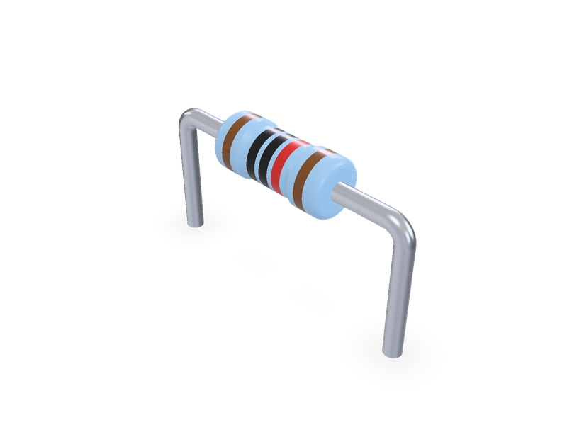
Axial leaded metal film resistor, Vishay Beyschlag MBA/SMA 0204, MBB/SMA 0207 and MBE/SMA 0414, with colour rings, horizontal or vertical.
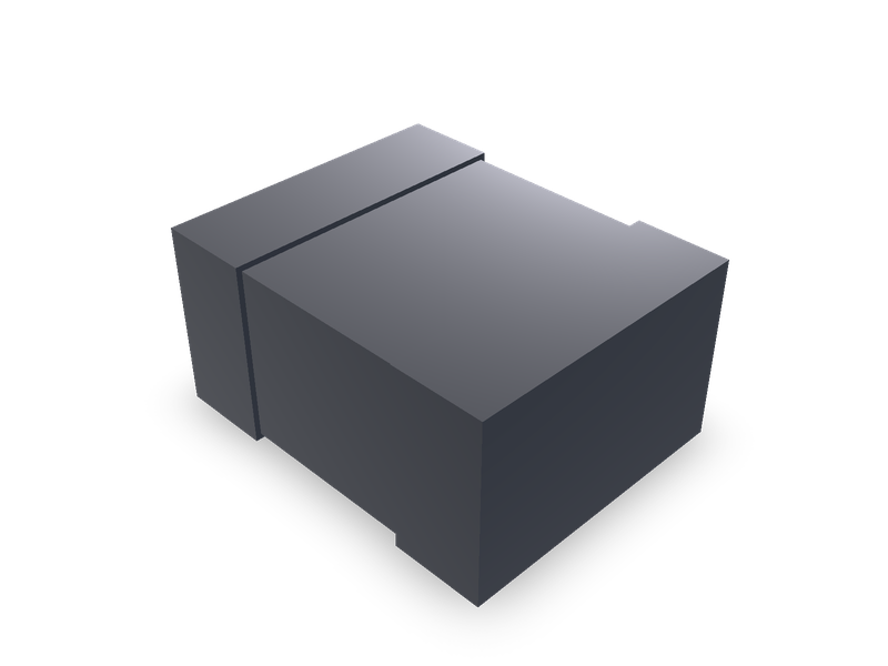
Power molded chip inductors in the Würth WE-PMCI sizes, 1.6 x 0.8 mm to 3.2 x 2.5 mm, by the maker's datasheets.
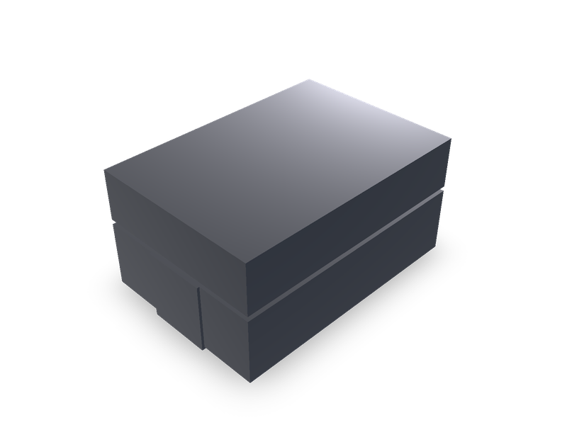
Shielded SMD flat-wire high-current inductors in the Würth WE-HCM sizes, 7 x 7 mm to 13.3 x 13.5 mm, by the maker's datasheets.