
STEVEMIT
steve/pin-socket
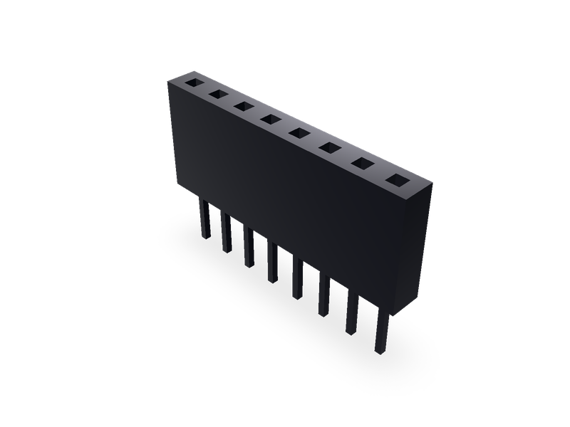
Pin socket (female header): 2.54 mm straight, 2.00 mm surface-mount, 1.27 mm surface-mount and right-angle, 1.00 mm straight and surface-mount, one or two rows.
D-sub connectors, standard density, 9, 15, 25 and 37 positions, male or female, vertical (NorComp 171) or right-angle .318" (NorComp 182).
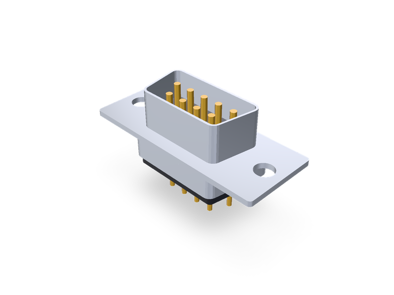
| 1 | """D-sub connector, standard density, 9, 15, 25 and 37 positions, male (pins) or female (sockets), vertical or right-angle through-hole: NorComp |
| 2 | 171 (vertical, dip solder) and 182 (right angle, .318" footprint). Pin 1 is at the origin; the first row (the longer one, on the D's wide side) |
| 3 | runs along +X on a male part and along -X on a female part, so the two mate pin for pin; the second row is 2.84 along -Y. |
| 4 | Vertical: the board is the XY plane, the D faces up (+Z), the tails go down through the board. Right-angle: the flange stands on the board |
| 5 | with the D facing -Y, the D's wide side up; the first row of tails is the one farther from the flange. Dimensions in the README.""" |
| 6 | from steve import Model |
| 7 | import math |
| 8 | |
| 9 | positions = 9 # Positions: 9, 15, 25 or 37 |
| 10 | gender = "male" # male (pins, plug) or female (sockets, receptacle) |
| 11 | mounting = "vertical" # vertical (NorComp 171) or right-angle (NorComp 182, .318") |
| 12 | detail = "full" # full: shell, insulator and contacts; simple: the metal shell only |
| 13 | |
| 14 | # NorComp, drawing 171-YYY-113RYY1 rev 18 (male, dip solder) and 171-YYY-213RYY1 rev 17 (female), sheet 1, table "DIMENSIONS (in/mm)", mm: |
| 15 | # positions: (A flange width, B mounting hole spacing, C D-shell width male, C female, D rear shell width, E D-shell height male, E female, |
| 16 | # F flange height). The 50-position size (three rows) isn't offered. |
| 17 | VERTICAL = { |
| 18 | 9: (30.80, 24.99, 16.92, 16.30, 19.20, 8.36, 7.90, 12.60), |
| 19 | 15: (39.15, 33.32, 25.25, 24.65, 27.70, 8.36, 7.90, 12.60), |
| 20 | 25: (53.00, 47.04, 38.96, 38.40, 41.10, 8.36, 7.90, 12.60), |
| 21 | 37: (69.30, 63.50, 55.42, 54.80, 57.30, 8.36, 7.90, 12.60), |
| 22 | } |
| 23 | # 171, sheet 1 views (mm): flange 0.90 thick; the D 6.00 in front of the flange; the rear shell 4.10 behind the flange and 10.90 high; the |
| 24 | # insulator 5.60 max behind the flange; the tails 4.80 beyond the insulator and 4.00 beyond its standoffs (the seating plane). |
| 25 | V_FLANGE, V_FRONT, V_REAR_SHELL, V_REAR_INSULATOR, V_REAR_HIGH, V_TAIL_PAST_INSULATOR, V_TAIL = 0.90, 6.00, 4.10, 5.60, 10.90, 4.80, 4.00 |
| 26 | # 171 sheet 2, recommended PCB layout (inch): the 25-position first row spans 2 x 0.652 over 12 pitches (pitch 0.1087" = 2.76 mm), the rows are |
| 27 | # 0.056 either side of the centre line (2.84 apart). |
| 28 | V_PITCH, ROW = 0.652 / 6 * 25.4, 0.112 * 25.4 |
| 29 | # NorComp, drawing 182-YYY-113RYY1 rev 16 (male) and 182-YYY-213RYY1 rev 18 (female), R/A .318", sheet 1, table "DIMENSIONS", mm: |
| 30 | # positions: (A flange width male, A female, B mounting hole spacing, C D-shell width male, C female). |
| 31 | RIGHT_ANGLE = { |
| 32 | 9: (30.80, 30.81, 24.99, 16.92, 16.30), |
| 33 | 15: (39.14, 39.14, 33.32, 25.25, 24.65), |
| 34 | 25: (53.04, 53.04, 47.04, 38.96, 38.40), |
| 35 | 37: (69.32, 69.32, 63.50, 55.40, 54.80), |
| 36 | } |
| 37 | # 182 sheet 1 views (mm): flange 12.55 high, its lower edge on the board; the D 6.0 (male) or 5.9 (female) in front of the flange; overall depth |
| 38 | # 18.51 (male) or 18.3 (female); the first row of tails 8.08 (.318") behind the flange's front face, the rows 2.84 apart, pitch 2.77; tails |
| 39 | # 0.64 square, 3.18 below the board; Ø 3.05 holes through the flange (hardware option 43, ".120 dia. hole", sheet 2). |
| 40 | RA_FLANGE_HIGH, RA_FRONT, RA_DEPTH, RA_ROW, RA_PITCH, RA_TAIL, RA_POST = 12.55, {"male": 6.0, "female": 5.9}, {"male": 18.51, "female": 18.3}, 8.08, 2.77, 3.18, 0.64 |
| 41 | HOLE = 3.05 |
| 42 | # NorComp panel cutout drawing (Panel_Cutout_D-Sub-Single): the D's sides lean 10 deg. |
| 43 | SIDE_ANGLE = 10.0 |
| 44 | # Proportions, for looks (README): shell sheet 0.4 thick; the D's corners rounded 0.15 x its height; the flange's corners 0.6; the male pins |
| 45 | # Ø 1.0 rising from an insulator 1.5 above the flange to 0.6 below the D's front edge; the female insulator flush with the D's front, its |
| 46 | # sockets Ø 1.0 and 4 deep; the vertical part's tails Ø 0.8 (the sheet's PCB hole is Ø 1.09); its rear insulator 0.6 inside the rear shell, |
| 47 | # with four Ø 1.5 standoffs; the right-angle part's insulator body the flange's full width and height. The 171 flange (0.90) is used for the 182. |
| 48 | SHEET, PIN, SOCKET_DEPTH, V_TAIL_D, STANDOFF_D = 0.4, 1.0, 4.0, 0.8, 1.5 |
| 49 | |
| 50 | if positions not in VERTICAL: |
| 51 | raise ValueError(f"positions: one of {', '.join(map(str, VERTICAL))}") |
| 52 | if gender not in ("male", "female") or mounting not in ("vertical", "right-angle"): |
| 53 | raise ValueError("gender: male or female; mounting: vertical or right-angle") |
| 54 | male = gender == "male" |
| 55 | vertical = mounting == "vertical" |
| 56 | first = (positions + 1) // 2 |
| 57 | side = 1 if male else -1 |
| 58 | if vertical: |
| 59 | A, B, C_m, C_f, D_rear, E_m, E_f, F = VERTICAL[positions] |
| 60 | C, E = (C_m, E_m) if male else (C_f, E_f) |
| 61 | pitch = V_PITCH |
| 62 | flange_front = V_TAIL_PAST_INSULATOR - V_TAIL + V_REAR_INSULATOR + V_FLANGE # seating plane to the flange's front face |
| 63 | cw = -ROW / 2 # cross-axis (Y) centre of the D |
| 64 | else: |
| 65 | A_m, A_f, B, C_m, C_f = RIGHT_ANGLE[positions] |
| 66 | A, C = (A_m, C_m) if male else (A_f, C_f) |
| 67 | E = VERTICAL[positions][5 if male else 6] # the 182 uses the same shell; its D height is on the 171 drawing |
| 68 | F = RA_FLANGE_HIGH |
| 69 | pitch = RA_PITCH |
| 70 | flange_front = RA_ROW + ROW # first row (y = 0) to the flange's front face, along -Y |
| 71 | cw = F / 2 # cross-axis (Z) centre of the D |
| 72 | cx = side * (first - 1) * pitch / 2 |
| 73 | front = flange_front + (V_FRONT if vertical else RA_FRONT[gender]) |
| 74 | flange_rear = flange_front - V_FLANGE |
| 75 | |
| 76 | |
| 77 | def rounded(points, r, n=5): |
| 78 | """A convex polygon (counter-clockwise) with its corners rounded to radius r.""" |
| 79 | out = [] |
| 80 | k = len(points) |
| 81 | for i in range(k): |
| 82 | px, py = points[i - 1] |
| 83 | vx, vy = points[i] |
| 84 | nx, ny = points[(i + 1) % k] |
| 85 | a = (px - vx, py - vy) |
| 86 | b = (nx - vx, ny - vy) |
| 87 | la, lb = math.hypot(*a), math.hypot(*b) |
| 88 | a, b = (a[0] / la, a[1] / la), (b[0] / lb, b[1] / lb) |
| 89 | theta = math.acos(max(-1.0, min(1.0, a[0] * b[0] + a[1] * b[1]))) |
| 90 | t = r / math.tan(theta / 2) |
| 91 | bis = (a[0] + b[0], a[1] + b[1]) |
| 92 | lbis = math.hypot(*bis) |
| 93 | c = (vx + bis[0] / lbis * r / math.sin(theta / 2), vy + bis[1] / lbis * r / math.sin(theta / 2)) |
| 94 | p0 = (vx + a[0] * t, vy + a[1] * t) |
| 95 | p1 = (vx + b[0] * t, vy + b[1] * t) |
| 96 | a0 = math.atan2(p0[1] - c[1], p0[0] - c[0]) |
| 97 | a1 = math.atan2(p1[1] - c[1], p1[0] - c[0]) |
| 98 | while a1 < a0: |
| 99 | a1 += 2 * math.pi |
| 100 | out += [(c[0] + r * math.cos(a0 + (a1 - a0) * j / n), c[1] + r * math.sin(a0 + (a1 - a0) * j / n)) for j in range(n + 1)] |
| 101 | return out |
| 102 | |
| 103 | |
| 104 | def d_shape(width, high, r, inset=0.0): |
| 105 | """The D: `width` across its wide side (+cross axis), sides leaning SIDE_ANGLE, shrunk by `inset` all round.""" |
| 106 | tan = math.tan(math.radians(SIDE_ANGLE)) |
| 107 | w = width - 2 * inset / math.cos(math.radians(SIDE_ANGLE)) |
| 108 | h = high - 2 * inset |
| 109 | top, bottom = w / 2, w / 2 - h * tan |
| 110 | pts = [(cx - bottom, cw - h / 2), (cx + bottom, cw - h / 2), (cx + top, cw + h / 2), (cx - top, cw + h / 2)] |
| 111 | return rounded(pts, max(r - inset, 0.1)) |
| 112 | |
| 113 | |
| 114 | def rect(w, h): |
| 115 | return [(cx - w / 2, cw - h / 2), (cx + w / 2, cw - h / 2), (cx + w / 2, cw + h / 2), (cx - w / 2, cw + h / 2)] |
| 116 | |
| 117 | |
| 118 | model = Model() |
| 119 | |
| 120 | |
| 121 | def prism(fid, pts, u0, u1, name, body, op="join"): |
| 122 | """A prism of the outline `pts` (x, cross) from u0 to u1 along the connector's axis (toward the mating face).""" |
| 123 | if vertical: |
| 124 | model.plane(f"{fid}_plane", on="XY", offset=u0, name=name) |
| 125 | else: |
| 126 | model.plane(f"{fid}_plane", on="XZ", offset=u0, name=name) # XZ at y = -u0; a positive extrude runs along -Y |
| 127 | with model.sketch(f"{fid}_sketch", on=f"{fid}_plane", name=name) as sk: |
| 128 | sk.polyline(f"{fid}_outline", pts, closed=True) |
| 129 | model.extrude(fid, f"{fid}_sketch", distance=u1 - u0, op=op, body=body, name=name) |
| 130 | |
| 131 | |
| 132 | def rods(fid, centres, d, u0, u1, name, body, op="new"): |
| 133 | if vertical: |
| 134 | model.plane(f"{fid}_plane", on="XY", offset=u0, name=name) |
| 135 | else: |
| 136 | model.plane(f"{fid}_plane", on="XZ", offset=u0, name=name) |
| 137 | with model.sketch(f"{fid}_sketch", on=f"{fid}_plane", name=name) as sk: |
| 138 | for i, (x, w) in enumerate(centres): |
| 139 | sk.circle(f"{fid}_{i}", (x, w), d / 2) |
| 140 | model.extrude(fid, f"{fid}_sketch", distance=u1 - u0, op=op, body=body, name=name) |
| 141 | |
| 142 | |
| 143 | corner = 0.15 * E |
| 144 | row_w = (cw + ROW / 2, cw - ROW / 2) # first and second row on the D's face |
| 145 | face = [(side * i * pitch, row_w[0]) for i in range(first)] + [(side * (i + 0.5) * pitch, row_w[1]) for i in range(positions - first)] |
| 146 | holes = [(cx - B / 2, cw), (cx + B / 2, cw)] |
| 147 | |
| 148 | # The metal shell: flange, the D in front of it and (vertical) the rear shell behind it. |
| 149 | prism("flange", rounded(rect(A, F), 0.6), flange_rear, flange_front, "Flange", "shell_body", op="new") |
| 150 | prism("d_shell", d_shape(C, E, corner), flange_front, front, "D shell", "shell_body") |
| 151 | if vertical: |
| 152 | prism("rear_shell", d_shape(D_rear, V_REAR_HIGH, corner), flange_rear - V_REAR_SHELL, flange_rear, "Rear shell", "shell_body") |
| 153 | if detail == "full": |
| 154 | prism("d_cavity", d_shape(C, E, corner, SHEET), flange_front, front, "D cavity", "shell_body", op="cut") |
| 155 | rods("mount_holes", holes, HOLE, flange_rear, flange_front, "Mounting holes", "shell_body", op="cut") |
| 156 | bodies = {"shell_body": ("steel-dc01", "#c9cdd2")} |
| 157 | |
| 158 | if detail == "full": |
| 159 | # Insulator: inside the D, and behind the flange. |
| 160 | if male: |
| 161 | prism("insulator_face", d_shape(C, E, corner, SHEET), flange_front, flange_front + 1.5, "Insulator", "insulator_body", op="new") |
| 162 | else: |
| 163 | prism("insulator_face", d_shape(C, E, corner, SHEET), flange_front, front, "Insulator", "insulator_body", op="new") |
| 164 | if vertical: |
| 165 | floor = V_TAIL_PAST_INSULATOR - V_TAIL |
| 166 | prism("insulator_rear", d_shape(D_rear, V_REAR_HIGH, corner, 0.6), floor, flange_rear - V_REAR_SHELL, "Rear insulator", "insulator_body") |
| 167 | tan = math.tan(math.radians(SIDE_ANGLE)) |
| 168 | hw, hh = (D_rear - 1.2) / 2 - (V_REAR_HIGH - 1.2) * tan - 1.6, (V_REAR_HIGH - 1.2) / 2 - 1.6 |
| 169 | rods("standoffs", [(cx - hw, cw - hh), (cx + hw, cw - hh), (cx - hw - 2 * hh * tan, cw + hh), (cx + hw + 2 * hh * tan, cw + hh)], |
| 170 | STANDOFF_D, 0.0, floor, "Standoffs", "insulator_body", op="join") |
| 171 | else: |
| 172 | back = flange_front - RA_DEPTH[gender] + RA_FRONT[gender] |
| 173 | prism("insulator_rear", rounded(rect(A, F), 0.6), back, flange_rear, "Insulator body", "insulator_body") |
| 174 | rods("body_holes", holes, HOLE, back, flange_rear, "Mounting holes", "insulator_body", op="cut") |
| 175 | bodies["insulator_body"] = ("pa6", "#1d1d1f") |
| 176 | # Contacts: male pins on the D's face, female sockets cut into the insulator; the tails below the board. |
| 177 | if male: |
| 178 | rods("pins", face, PIN, flange_front + 1.5, front - 0.6, "Pins", "contacts_body") |
| 179 | else: |
| 180 | rods("sockets", face, PIN, front - SOCKET_DEPTH, front, "Sockets", "insulator_body", op="cut") |
| 181 | tails = [(side * i * pitch, 0.0) for i in range(first)] + [(side * (i + 0.5) * pitch, -ROW) for i in range(positions - first)] |
| 182 | if vertical: |
| 183 | model.plane("tails_plane", on="XY", offset=-V_TAIL, name="Tails") |
| 184 | with model.sketch("tails_sketch", on="tails_plane", name="Tails") as sk: |
| 185 | for i, (x, y) in enumerate(tails): |
| 186 | sk.circle(f"tail_{i}", (x, y), V_TAIL_D / 2) |
| 187 | model.extrude("tails", "tails_sketch", distance=V_TAIL + V_TAIL_PAST_INSULATOR - V_TAIL, op="join" if male else "new", body="contacts_body", name="Tails") |
| 188 | else: |
| 189 | model.plane("tails_plane", on="XY", offset=-RA_TAIL, name="Tails") |
| 190 | with model.sketch("tails_sketch", on="tails_plane", name="Tails") as sk: |
| 191 | for i, (x, y) in enumerate(tails): |
| 192 | sk.rect(f"tail_{i}", (x - RA_POST / 2, y - RA_POST / 2), (x + RA_POST / 2, y + RA_POST / 2)) |
| 193 | model.extrude("tails", "tails_sketch", distance=RA_TAIL + 1.0, op="join" if male else "new", body="contacts_body", name="Tails") |
| 194 | bodies["contacts_body"] = ("brass", "#d4a94a") |
| 195 | |
| 196 | # Materials, for looks and a rough mass: the shell is nickel-plated SPCC (cold-rolled steel, DC01); the insulator PA6T / PA9T, so nylon (PA6); |
| 197 | # the contacts gold-plated brass. |
| 198 | for body, (material, colour) in bodies.items(): |
| 199 | model.material(material, bodies=[body], color=colour) |
| 200 | result = model.result() |
| 201 |
| 1 | name = "steve/dsub-connector" |
| 2 | version = "1.0.0" |
| 3 | runtime = "steve" |
| 4 | license = "MIT" |
| 5 | summary = "D-sub connectors, standard density, 9, 15, 25 and 37 positions, male or female, vertical (NorComp 171) or right-angle .318\" (NorComp 182)." |
| 6 | description = """D-sub (D-subminiature) board connector with the standard shell, from NorComp's drawings: the stamped steel shell with its flange and mounting holes, the D, the insulator and the contacts. Vertical dip-solder (NorComp 171) or right-angle with the .318" footprint (NorComp 182), male (pins) or female (sockets). Pin 1 at the origin. See the README.""" |
| 7 | tags = ["d-sub", "dsub", "connector", "de-9", "db-25", "through-hole", "electronics"] |
| 8 | |
| 9 | [parameters.positions] |
| 10 | type = "choice" |
| 11 | default = 9 |
| 12 | choices = [9, 15, 25, 37] |
| 13 | label = "Positions" |
| 14 | description = "Shell size: 9 (E), 15 (A), 25 (B) or 37 (C)." |
| 15 | |
| 16 | [parameters.gender] |
| 17 | type = "choice" |
| 18 | default = "male" |
| 19 | choices = ["male", "female"] |
| 20 | label = "Gender" |
| 21 | description = "male: pins (plug). female: sockets (receptacle)." |
| 22 | |
| 23 | [parameters.mounting] |
| 24 | type = "choice" |
| 25 | default = "vertical" |
| 26 | choices = ["vertical", "right-angle"] |
| 27 | label = "Mounting" |
| 28 | description = "vertical: NorComp 171, the D facing up. right-angle: NorComp 182, .318\" footprint, the flange standing on the board." |
| 29 | |
| 30 | [parameters.detail] |
| 31 | type = "choice" |
| 32 | default = "full" |
| 33 | choices = ["full", "simple"] |
| 34 | label = "Detail" |
| 35 | description = "full: shell, insulator and contacts. simple: the metal shell only, for big assemblies." |
| 36 | |
| 37 | [[presets]] |
| 38 | id = "171-9-M" |
| 39 | title = "NorComp 171, D-sub 9 positions, male (plug, pins), vertical" |
| 40 | params = { positions = 9, gender = "male", mounting = "vertical" } |
| 41 | aliases = ["NorComp 171-009-1", "DE-9P vertical", "DSUB-9 male vertical", "D-sub 9 male vertical", "DE9 male vertical", "171-009-113R001", "NorComp 171, D-sub 9 positions, male (plug, pins), vertical"] |
| 42 | standard = "NorComp 171" |
| 43 | |
| 44 | [[presets]] |
| 45 | id = "171-9-F" |
| 46 | title = "NorComp 171, D-sub 9 positions, female (receptacle, sockets), vertical" |
| 47 | params = { positions = 9, gender = "female", mounting = "vertical" } |
| 48 | aliases = ["NorComp 171-009-2", "DE-9S vertical", "DSUB-9 female vertical", "D-sub 9 female vertical", "DE9 female vertical", "171-009-213R001", "NorComp 171, D-sub 9 positions, female (receptacle, sockets), vertical"] |
| 49 | standard = "NorComp 171" |
| 50 | |
| 51 | [[presets]] |
| 52 | id = "171-15-M" |
| 53 | title = "NorComp 171, D-sub 15 positions, male (plug, pins), vertical" |
| 54 | params = { positions = 15, gender = "male", mounting = "vertical" } |
| 55 | aliases = ["NorComp 171-015-1", "DA-15P vertical", "DSUB-15 male vertical", "D-sub 15 male vertical", "DA15 male vertical", "171-015-113R001", "NorComp 171, D-sub 15 positions, male (plug, pins), vertical"] |
| 56 | standard = "NorComp 171" |
| 57 | |
| 58 | [[presets]] |
| 59 | id = "171-15-F" |
| 60 | title = "NorComp 171, D-sub 15 positions, female (receptacle, sockets), vertical" |
| 61 | params = { positions = 15, gender = "female", mounting = "vertical" } |
| 62 | aliases = ["NorComp 171-015-2", "DA-15S vertical", "DSUB-15 female vertical", "D-sub 15 female vertical", "DA15 female vertical", "171-015-213R001", "NorComp 171, D-sub 15 positions, female (receptacle, sockets), vertical"] |
| 63 | standard = "NorComp 171" |
| 64 | |
| 65 | [[presets]] |
| 66 | id = "171-25-M" |
| 67 | title = "NorComp 171, D-sub 25 positions, male (plug, pins), vertical" |
| 68 | params = { positions = 25, gender = "male", mounting = "vertical" } |
| 69 | aliases = ["NorComp 171-025-1", "DB-25P vertical", "DSUB-25 male vertical", "D-sub 25 male vertical", "DB25 male vertical", "171-025-113R001", "NorComp 171, D-sub 25 positions, male (plug, pins), vertical"] |
| 70 | standard = "NorComp 171" |
| 71 | |
| 72 | [[presets]] |
| 73 | id = "171-25-F" |
| 74 | title = "NorComp 171, D-sub 25 positions, female (receptacle, sockets), vertical" |
| 75 | params = { positions = 25, gender = "female", mounting = "vertical" } |
| 76 | aliases = ["NorComp 171-025-2", "DB-25S vertical", "DSUB-25 female vertical", "D-sub 25 female vertical", "DB25 female vertical", "171-025-213R001", "NorComp 171, D-sub 25 positions, female (receptacle, sockets), vertical"] |
| 77 | standard = "NorComp 171" |
| 78 | |
| 79 | [[presets]] |
| 80 | id = "171-37-M" |
| 81 | title = "NorComp 171, D-sub 37 positions, male (plug, pins), vertical" |
| 82 | params = { positions = 37, gender = "male", mounting = "vertical" } |
| 83 | aliases = ["NorComp 171-037-1", "DC-37P vertical", "DSUB-37 male vertical", "D-sub 37 male vertical", "DC37 male vertical", "171-037-113R001", "NorComp 171, D-sub 37 positions, male (plug, pins), vertical"] |
| 84 | standard = "NorComp 171" |
| 85 | |
| 86 | [[presets]] |
| 87 | id = "171-37-F" |
| 88 | title = "NorComp 171, D-sub 37 positions, female (receptacle, sockets), vertical" |
| 89 | params = { positions = 37, gender = "female", mounting = "vertical" } |
| 90 | aliases = ["NorComp 171-037-2", "DC-37S vertical", "DSUB-37 female vertical", "D-sub 37 female vertical", "DC37 female vertical", "171-037-213R001", "NorComp 171, D-sub 37 positions, female (receptacle, sockets), vertical"] |
| 91 | standard = "NorComp 171" |
| 92 | |
| 93 | [[presets]] |
| 94 | id = "182-9-M" |
| 95 | title = "NorComp 182, D-sub 9 positions, male (plug, pins), right angle .318\"" |
| 96 | params = { positions = 9, gender = "male", mounting = "right-angle" } |
| 97 | aliases = ["NorComp 182-009-1", "DE-9P right-angle", "DSUB-9 male right-angle", "D-sub 9 male right-angle", "DE9 male right-angle", "182-009-113R431"] |
| 98 | standard = "NorComp 182" |
| 99 | |
| 100 | [[presets]] |
| 101 | id = "182-9-F" |
| 102 | title = "NorComp 182, D-sub 9 positions, female (receptacle, sockets), right angle .318\"" |
| 103 | params = { positions = 9, gender = "female", mounting = "right-angle" } |
| 104 | aliases = ["NorComp 182-009-2", "DE-9S right-angle", "DSUB-9 female right-angle", "D-sub 9 female right-angle", "DE9 female right-angle", "182-009-213R431"] |
| 105 | standard = "NorComp 182" |
| 106 | |
| 107 | [[presets]] |
| 108 | id = "182-15-M" |
| 109 | title = "NorComp 182, D-sub 15 positions, male (plug, pins), right angle .318\"" |
| 110 | params = { positions = 15, gender = "male", mounting = "right-angle" } |
| 111 | aliases = ["NorComp 182-015-1", "DA-15P right-angle", "DSUB-15 male right-angle", "D-sub 15 male right-angle", "DA15 male right-angle", "182-015-113R431"] |
| 112 | standard = "NorComp 182" |
| 113 | |
| 114 | [[presets]] |
| 115 | id = "182-15-F" |
| 116 | title = "NorComp 182, D-sub 15 positions, female (receptacle, sockets), right angle .318\"" |
| 117 | params = { positions = 15, gender = "female", mounting = "right-angle" } |
| 118 | aliases = ["NorComp 182-015-2", "DA-15S right-angle", "DSUB-15 female right-angle", "D-sub 15 female right-angle", "DA15 female right-angle", "182-015-213R431"] |
| 119 | standard = "NorComp 182" |
| 120 | |
| 121 | [[presets]] |
| 122 | id = "182-25-M" |
| 123 | title = "NorComp 182, D-sub 25 positions, male (plug, pins), right angle .318\"" |
| 124 | params = { positions = 25, gender = "male", mounting = "right-angle" } |
| 125 | aliases = ["NorComp 182-025-1", "DB-25P right-angle", "DSUB-25 male right-angle", "D-sub 25 male right-angle", "DB25 male right-angle", "182-025-113R431"] |
| 126 | standard = "NorComp 182" |
| 127 | |
| 128 | [[presets]] |
| 129 | id = "182-25-F" |
| 130 | title = "NorComp 182, D-sub 25 positions, female (receptacle, sockets), right angle .318\"" |
| 131 | params = { positions = 25, gender = "female", mounting = "right-angle" } |
| 132 | aliases = ["NorComp 182-025-2", "DB-25S right-angle", "DSUB-25 female right-angle", "D-sub 25 female right-angle", "DB25 female right-angle", "182-025-213R431"] |
| 133 | standard = "NorComp 182" |
| 134 | |
| 135 | [[presets]] |
| 136 | id = "182-37-M" |
| 137 | title = "NorComp 182, D-sub 37 positions, male (plug, pins), right angle .318\"" |
| 138 | params = { positions = 37, gender = "male", mounting = "right-angle" } |
| 139 | aliases = ["NorComp 182-037-1", "DC-37P right-angle", "DSUB-37 male right-angle", "D-sub 37 male right-angle", "DC37 male right-angle", "182-037-113R431"] |
| 140 | standard = "NorComp 182" |
| 141 | |
| 142 | [[presets]] |
| 143 | id = "182-37-F" |
| 144 | title = "NorComp 182, D-sub 37 positions, female (receptacle, sockets), right angle .318\"" |
| 145 | params = { positions = 37, gender = "female", mounting = "right-angle" } |
| 146 | aliases = ["NorComp 182-037-2", "DC-37S right-angle", "DSUB-37 female right-angle", "D-sub 37 female right-angle", "DC37 female right-angle", "182-037-213R431"] |
| 147 | standard = "NorComp 182" |
| 148 | |
| 149 | [[presets]] |
| 150 | id = "171-25-M-simple" |
| 151 | title = "NorComp 171, D-sub 25 positions, male (plug, pins), vertical, simple" |
| 152 | params = { positions = 25, gender = "male", mounting = "vertical", detail = "simple" } |
| 153 | aliases = ["NorComp 171-025-1 simple"] |
| 154 | standard = "NorComp 171" |
| 155 |
A D-sub (D-subminiature) board connector, standard density, with the standard shell: NorComp's 171 series (vertical, dip solder) and 182 series (right angle, .318" footprint). The stamped steel shell has its flange with two mounting holes, the D in front of the flange and, on the vertical part, the rear shell behind it. Inside are the insulator and the contacts: pins on a male part (plug), sockets on a female part (receptacle).
positions: 9, 15, 25 or 37, the shell sizes E, A, B and C (DE-9, DA-15, DB-25, DC-37).gender: male or female.mounting: vertical (NorComp 171, the D facing up) or right-angle (NorComp 182, the flange standing on the board, the D facing -Y).detail: full, or simple for the metal shell only.Pin 1 is at the origin. The first row, the longer one, is on the D's wide side. It runs along +X on a male part and along -X on a female part, so a plug and a receptacle mate pin for pin. The second row is 2.84 along -Y. On the right-angle part, the first row is the one farther from the flange.
| Positions | Flange A | Hole spacing B | D width C, male / female | D height E, male / female | Rear shell D (171) |
|---|---|---|---|---|---|
| 9 | 30.80 | 24.99 | 16.92 / 16.30 | 8.36 / 7.90 | 19.20 |
| 15 | 39.15 | 33.32 | 25.25 / 24.65 | 8.36 / 7.90 | 27.70 |
| 25 | 53.00 | 47.04 | 38.96 / 38.40 | 8.36 / 7.90 | 41.10 |
| 37 | 69.30 | 63.50 | 55.42 / 54.80 | 8.36 / 7.90 | 57.30 |
These are the 171 values. The 182 drawings give A as 30.80 (30.81 female), 39.14, 53.04 and 69.32, and C for the 37-position male as 55.40. part.py uses each drawing's own values.
Vertical (171). The flange is 12.60 high and 0.90 thick. The D stands 6.00 in front of the flange. Behind the flange, the rear shell is 4.10 deep and 10.90 high, and the insulator ends 5.60 max behind the flange. The tails reach 4.80 beyond the insulator and 4.00 beyond its standoffs, which sit on the board. So the seating plane is 0.8 below the insulator, the flange is 6.4 to 7.3 above the board, and the D's front is 13.3 above it. The pitch is 2.76 (0.1087"), with the rows 2.84 apart.
Right angle (182, .318"). The flange is 12.55 high, with its lower edge on the board. The D stands 6.0 (male) or 5.9 (female) in front of the flange. The overall depth is 18.51 (male) or 18.3 (female). The first row of tails nearest the flange is 8.08 (.318") behind the flange's front face, and the rows are 2.84 apart at a pitch of 2.77. The tails are 0.64 square and 3.18 long below the board. The flange has Ø 3.05 holes, which is hardware option 43, ".120 dia. hole".
NorComp drawings, from NorComp's own site (content.norcomp.net, rohspdfs/Connectors/...):
Proportions, for looks only. The drawings show these but don't dimension them:
The 50-position size, which has three rows, isn't offered.
The catalogue's DSUB-<n>_<Pins|Male|Socket|Female>_<Vertical|Horizontal>_... models name no maker. Every maker builds the same standard shell, and NorComp's drawings follow it, but the reference models' shells are narrower. Measured on the reference models:
So each model whose pin count, gender and mounting NorComp's drawings have maps to NorComp's part, 28 of the 104:
P2.77x2.84mm, with or without _MountingHoles (9, 15, 25 and 37 positions, pins, male, socket and female), maps to the 171.EdgePinOffset7.70mm_Housed_MountingHolesOffset9.12mm (9, 15, 25 and 37 positions, pins and socket), maps to the 182. Measured on the 25-socket model: the flange's front face is 7.98 in front of the nearer row of pins, where the 182 has .318" (8.08). The mounting holes are 1.42 behind that row, as on the 182. The flange is 53.10 x 12.5, against 53.04 x 12.55, and the D is 6.1 deep, against 5.9.These stay "no table read yet" (COVERAGE.md) until a drawing for them is read:
P2.77x2.54mm models.| 1 | # D-sub connector |
| 2 | |
| 3 | A D-sub (D-subminiature) board connector, standard density, with the standard shell: NorComp's 171 series (vertical, dip solder) and 182 series (right angle, .318" footprint). The stamped steel shell has its flange with two mounting holes, the D in front of the flange and, on the vertical part, the rear shell behind it. Inside are the insulator and the contacts: pins on a male part (plug), sockets on a female part (receptacle). |
| 4 | |
| 5 | - `positions`: 9, 15, 25 or 37, the shell sizes E, A, B and C (DE-9, DA-15, DB-25, DC-37). |
| 6 | - `gender`: `male` or `female`. |
| 7 | - `mounting`: `vertical` (NorComp 171, the D facing up) or `right-angle` (NorComp 182, the flange standing on the board, the D facing -Y). |
| 8 | - `detail`: `full`, or `simple` for the metal shell only. |
| 9 | |
| 10 | Pin 1 is at the origin. The first row, the longer one, is on the D's wide side. It runs along +X on a male part and along -X on a female part, so a plug and a receptacle mate pin for pin. The second row is 2.84 along -Y. On the right-angle part, the first row is the one farther from the flange. |
| 11 | |
| 12 | | Positions | Flange A | Hole spacing B | D width C, male / female | D height E, male / female | Rear shell D (171) | |
| 13 | |---|---|---|---|---|---| |
| 14 | | 9 | 30.80 | 24.99 | 16.92 / 16.30 | 8.36 / 7.90 | 19.20 | |
| 15 | | 15 | 39.15 | 33.32 | 25.25 / 24.65 | 8.36 / 7.90 | 27.70 | |
| 16 | | 25 | 53.00 | 47.04 | 38.96 / 38.40 | 8.36 / 7.90 | 41.10 | |
| 17 | | 37 | 69.30 | 63.50 | 55.42 / 54.80 | 8.36 / 7.90 | 57.30 | |
| 18 | |
| 19 | These are the 171 values. The 182 drawings give A as 30.80 (30.81 female), 39.14, 53.04 and 69.32, and C for the 37-position male as 55.40. `part.py` uses each drawing's own values. |
| 20 | |
| 21 | **Vertical (171).** The flange is 12.60 high and 0.90 thick. The D stands 6.00 in front of the flange. Behind the flange, the rear shell is 4.10 deep and 10.90 high, and the insulator ends 5.60 max behind the flange. The tails reach 4.80 beyond the insulator and 4.00 beyond its standoffs, which sit on the board. So the seating plane is 0.8 below the insulator, the flange is 6.4 to 7.3 above the board, and the D's front is 13.3 above it. The pitch is 2.76 (0.1087"), with the rows 2.84 apart. |
| 22 | |
| 23 | **Right angle (182, .318").** The flange is 12.55 high, with its lower edge on the board. The D stands 6.0 (male) or 5.9 (female) in front of the flange. The overall depth is 18.51 (male) or 18.3 (female). The first row of tails nearest the flange is 8.08 (.318") behind the flange's front face, and the rows are 2.84 apart at a pitch of 2.77. The tails are 0.64 square and 3.18 long below the board. The flange has Ø 3.05 holes, which is hardware option 43, ".120 dia. hole". |
| 24 | |
| 25 | ## Source |
| 26 | |
| 27 | NorComp drawings, from NorComp's own site (content.norcomp.net, `rohspdfs/Connectors/...`): |
| 28 | |
| 29 | - **171-YYY-113RYY1, rev 18** (male, dip solder, stamped) and **171-YYY-213RYY1, rev 17** (female). Sheet 1 has the table "DIMENSIONS (in/mm)" (A to F, by positions) and the side views: 0.90 flange, 6.00 D, 4.10 rear shell, 5.60 max insulator, 10.90 rear height, and 4.80 and 4.00 tails. Sheet 2 has the recommended PCB layout: the pin coordinates (25 positions: first row ±0.652 over 12 pitches; rows 0.056 either side of the centre line) and the Ø 0.043 tail holes. The materials are PA6T insulator, gold-plated brass contacts and a nickel-plated steel shell. |
| 30 | - **182-YYY-113RYY1, rev 16** (R/A .318", male) and **182-YYY-213RYY1, rev 18** (female). Sheet 1 has the table "DIMENSIONS" (A to D) and these views: 12.55 flange, 6.0 / 5.9 D, 18.51 / 18.3 depth, 0.318 [8.08] row, 0.109 [2.77] pitch, 0.112 [2.84] rows, 0.64 square tails, 3.18 below the board, and Ø 3.05 holes. Sheet 2 has the hardware options (43: metal shell, .120" hole). The materials are a nickel-plated SPCC shell, PA9T insulator and gold-plated brass contacts. The 182 drawings don't give the D's height. The 182 is built on the same standard shell (its A, B and C are the 171's), so the 171's E is used. |
| 31 | - **Panel_Cutout_D-Sub-Single**: the D's sides lean 10°. |
| 32 | |
| 33 | **Proportions, for looks only.** The drawings show these but don't dimension them: |
| 34 | |
| 35 | - The shell sheet is 0.4 thick. The D's corners are rounded to 0.15 x its height, and the flange's corners to 0.6. The rear shell (171) is drawn as the same 10° D. |
| 36 | - The male pins are Ø 1.0. They rise from an insulator face 1.5 in front of the flange to 0.6 below the D's front edge. The female insulator is flush with the D's front, with Ø 1.0 sockets 4 deep. |
| 37 | - On the 171, the tails are Ø 0.8, under the sheet's Ø 1.09 PCB hole. The rear insulator is 0.6 inside the rear shell, with four Ø 1.5 standoffs, 0.8 high, under it. |
| 38 | - On the 182, the insulator body is as wide and high as the flange, with the mounting holes through it. The flange is 0.90 thick, as on the 171. |
| 39 | - Materials are for looks and a rough mass. The shell is SPCC (cold-rolled steel, DC01), the insulator is nylon (PA6, for PA6T / PA9T) and the contacts are brass. |
| 40 | |
| 41 | The 50-position size, which has three rows, isn't offered. |
| 42 | |
| 43 | ## Catalogue models |
| 44 | |
| 45 | The catalogue's `DSUB-<n>_<Pins|Male|Socket|Female>_<Vertical|Horizontal>_...` models name no maker. Every maker builds the same standard shell, and NorComp's drawings follow it, but the reference models' shells are narrower. Measured on the reference models: |
| 46 | |
| 47 | - The D shell is 16.56 wide for the 9-pin plug, 15.92 for the 9-pin socket and 37.92 for the 25-pin socket. NorComp gives 16.92, 16.30 and 38.40, so the models are 0.3 to 0.5 mm narrower than the standard shell. The models are wrong, not another part. |
| 48 | - The vertical 9-pin plug's flange is 12.5 high and 4.2 to 4.7 above the board, with the D's front at 10.5 and 8.3 high. On NorComp's part, the flange is 12.60 high and 6.4 to 7.3 above the board, with the D's front at 13.3 and 8.36 high. |
| 49 | - The vertical models' pitch is 2.77. NorComp's layout gives 0.1087" (2.76). |
| 50 | |
| 51 | So each model whose pin count, gender and mounting NorComp's drawings have maps to NorComp's part, 28 of the 104: |
| 52 | |
| 53 | - **Vertical**, `P2.77x2.84mm`, with or without `_MountingHoles` (9, 15, 25 and 37 positions, pins, male, socket and female), maps to the 171. |
| 54 | - **Horizontal**, `EdgePinOffset7.70mm_Housed_MountingHolesOffset9.12mm` (9, 15, 25 and 37 positions, pins and socket), maps to the 182. Measured on the 25-socket model: the flange's front face is 7.98 in front of the nearer row of pins, where the 182 has .318" (8.08). The mounting holes are 1.42 behind that row, as on the 182. The flange is 53.10 x 12.5, against 53.04 x 12.55, and the D is 6.1 deep, against 5.9. |
| 55 | |
| 56 | These stay "no table read yet" (`COVERAGE.md`) until a drawing for them is read: |
| 57 | |
| 58 | - the high-density models (15, 26, 44 and 62 positions); |
| 59 | - the other right-angle footprints: edge offsets 4.94, 9.40, 9.90 and 14.56, including the unhoused 9.40 models, which measured 9.7 from the flange to the nearer row; |
| 60 | - the `P2.77x2.54mm` models. |
| 61 |
D-sub (D-subminiature) board connector with the standard shell, from NorComp's drawings: the stamped steel shell with its flange and mounting holes, the D, the insulator and the contacts. Vertical dip-solder (NorComp 171) or right-angle with the .318" footprint (NorComp 182), male (pins) or female (sockets). Pin 1 at the origin. See the README.
A D-sub (D-subminiature) board connector, standard density, with the standard shell: NorComp's 171 series (vertical, dip solder) and 182 series (right angle, .318" footprint). The stamped steel shell has its flange with two mounting holes, the D in front of the flange and, on the vertical part, the rear shell behind it. Inside are the insulator and the contacts: pins on a male part (plug), sockets on a female part (receptacle).
positions: 9, 15, 25 or 37, the shell sizes E, A, B and C (DE-9, DA-15, DB-25, DC-37).gender: male or female.mounting: vertical (NorComp 171, the D facing up) or right-angle (NorComp 182, the flange standing on the board, the D facing -Y).detail: full, or simple for the metal shell only.Pin 1 is at the origin. The first row, the longer one, is on the D's wide side. It runs along +X on a male part and along -X on a female part, so a plug and a receptacle mate pin for pin. The second row is 2.84 along -Y. On the right-angle part, the first row is the one farther from the flange.
| Positions | Flange A | Hole spacing B | D width C, male / female | D height E, male / female | Rear shell D (171) |
|---|---|---|---|---|---|
| 9 | 30.80 | 24.99 | 16.92 / 16.30 | 8.36 / 7.90 | 19.20 |
| 15 | 39.15 | 33.32 | 25.25 / 24.65 | 8.36 / 7.90 | 27.70 |
| 25 | 53.00 | 47.04 | 38.96 / 38.40 | 8.36 / 7.90 | 41.10 |
| 37 | 69.30 | 63.50 | 55.42 / 54.80 | 8.36 / 7.90 | 57.30 |
These are the 171 values. The 182 drawings give A as 30.80 (30.81 female), 39.14, 53.04 and 69.32, and C for the 37-position male as 55.40. part.py uses each drawing's own values.
Vertical (171). The flange is 12.60 high and 0.90 thick. The D stands 6.00 in front of the flange. Behind the flange, the rear shell is 4.10 deep and 10.90 high, and the insulator ends 5.60 max behind the flange. The tails reach 4.80 beyond the insulator and 4.00 beyond its standoffs, which sit on the board. So the seating plane is 0.8 below the insulator, the flange is 6.4 to 7.3 above the board, and the D's front is 13.3 above it. The pitch is 2.76 (0.1087"), with the rows 2.84 apart.
Right angle (182, .318"). The flange is 12.55 high, with its lower edge on the board. The D stands 6.0 (male) or 5.9 (female) in front of the flange. The overall depth is 18.51 (male) or 18.3 (female). The first row of tails nearest the flange is 8.08 (.318") behind the flange's front face, and the rows are 2.84 apart at a pitch of 2.77. The tails are 0.64 square and 3.18 long below the board. The flange has Ø 3.05 holes, which is hardware option 43, ".120 dia. hole".
NorComp drawings, from NorComp's own site (content.norcomp.net, rohspdfs/Connectors/...):
Proportions, for looks only. The drawings show these but don't dimension them:
The 50-position size, which has three rows, isn't offered.
The catalogue's DSUB-<n>_<Pins|Male|Socket|Female>_<Vertical|Horizontal>_... models name no maker. Every maker builds the same standard shell, and NorComp's drawings follow it, but the reference models' shells are narrower. Measured on the reference models:
So each model whose pin count, gender and mounting NorComp's drawings have maps to NorComp's part, 28 of the 104:
P2.77x2.84mm, with or without _MountingHoles (9, 15, 25 and 37 positions, pins, male, socket and female), maps to the 171.EdgePinOffset7.70mm_Housed_MountingHolesOffset9.12mm (9, 15, 25 and 37 positions, pins and socket), maps to the 182. Measured on the 25-socket model: the flange's front face is 7.98 in front of the nearer row of pins, where the 182 has .318" (8.08). The mounting holes are 1.42 behind that row, as on the 182. The flange is 53.10 x 12.5, against 53.04 x 12.55, and the D is 6.1 deep, against 5.9.These stay "no table read yet" (COVERAGE.md) until a drawing for them is read:
P2.77x2.54mm models.Pin socket (female header): 2.54 mm straight, 2.00 mm surface-mount, 1.27 mm surface-mount and right-angle, 1.00 mm straight and surface-mount, one or two rows.
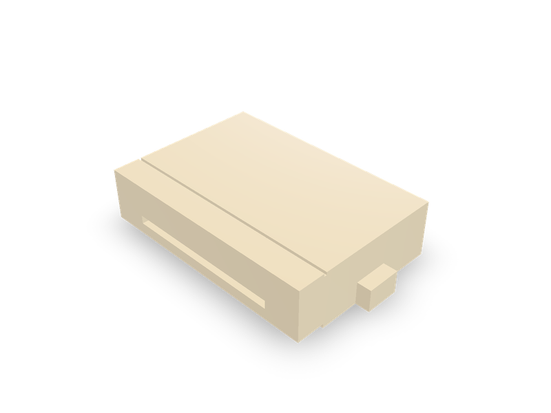
Hirose FH12 0.5 mm pitch FPC/FFC connectors, right angle, bottom contact, flip lock, 6 to 53 contacts, by the maker's drawing.
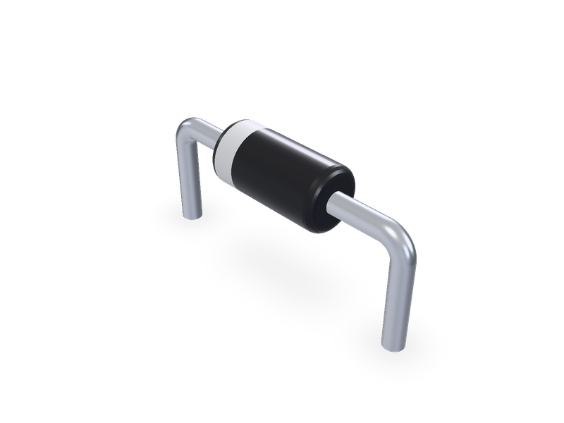
Axial leaded diodes in Vishay's DO-35, DO-41, DO-15, DO-201AD and P600 packages, with the cathode band, horizontal or vertical.
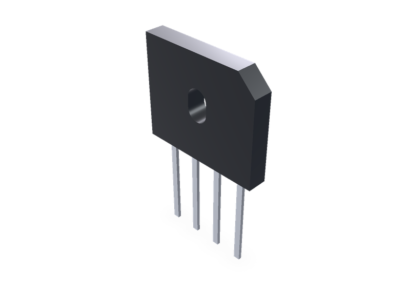
Single-phase bridge rectifiers in Vishay's through-hole cases: GBL, GBU, KBL and KBU in-line, KBPC1 and KBPC6 square, from Vishay's data sheets.