
STEVEMIT
littletechbird/dirac-belt
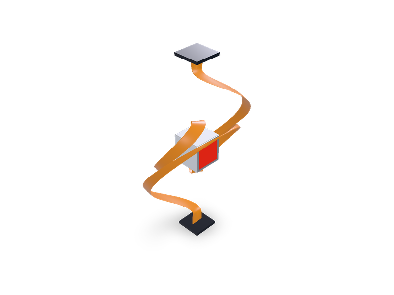
Dirac belt (belt trick): a cube tied to anchor pads by ribbons, posed at any moment of a 720 degree untangle.
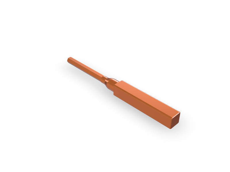
Primary injection test pins (tulips) for molded case circuit breakers: hex lug end, tulip flare, rounded-square clamp end, four sizes.
| 1 | """Primary injection test pin ("tulip") for testing molded case circuit breakers. |
| 2 | |
| 3 | One end is a milled hex that slides through the breaker's terminal cover into the set-screw box lug. A short |
| 4 | round neck blends through a tangent "tulip" flare into the full round body, so there is no sharp shoulder where |
| 5 | the pin levers against the lug mouth. The other end is a solid rounded-square bar (no holes) that the test |
| 6 | cable's lug is clamped to with vise-grips. The whole pin is turned and milled from one square bar of C18150 or |
| 7 | C18200 copper alloy, TH04 temper, left bare. |
| 8 | |
| 9 | `size` picks one of four sizes (the hex fits the smallest maximum wire in its frame range, the hex length clears |
| 10 | the deepest cover found plus the lug depth plus 0.25 in). `hex_length` and `square_length` can be overridden. |
| 11 | Pin axis along +x, hex tip at the origin, a hex corner pointing +z. Dimensions are set in inches; the model is |
| 12 | built in mm. |
| 13 | """ |
| 14 | import math |
| 15 | |
| 16 | import cadquery as cq |
| 17 | from steve import Model |
| 18 | |
| 19 | size = "2" # Size |
| 20 | hex_length = 0 # in Hex length override (0 = size default) |
| 21 | square_length = 4.0 # in Square clamp end length |
| 22 | |
| 23 | IN = 25.4 |
| 24 | SIZES = { |
| 25 | # hex across flats, hex length, neck length, flare length, body length, square width, corner radius, body dia |
| 26 | "1": dict(AF=0.3125, Lh=2.50, Ln=0.25, Lf=0.50, Lb=0.50, sq=0.75, rc=0.09, Db=0.70), |
| 27 | "2": dict(AF=0.375, Lh=3.25, Ln=0.25, Lf=0.50, Lb=0.50, sq=0.75, rc=0.09, Db=0.70), |
| 28 | "3": dict(AF=0.500, Lh=3.75, Ln=0.25, Lf=0.625, Lb=0.50, sq=1.00, rc=0.125, Db=0.94), |
| 29 | "4": dict(AF=0.625, Lh=4.00, Ln=0.25, Lf=0.625, Lb=0.50, sq=1.00, rc=0.125, Db=0.94), |
| 30 | } |
| 31 | s = dict(SIZES[str(size)]) |
| 32 | if hex_length: |
| 33 | if not 1.0 <= hex_length <= 8.0: |
| 34 | raise ValueError("hex_length must be 0 (size default) or between 1 and 8 in.") |
| 35 | s["Lh"] = float(hex_length) |
| 36 | if not 1.0 <= square_length <= 12.0: |
| 37 | raise ValueError("square_length must be between 1 and 12 in.") |
| 38 | LSQ = float(square_length) |
| 39 | |
| 40 | AF, Lh = s["AF"], s["Lh"] |
| 41 | AC = AF / math.cos(math.radians(30)) # across corners |
| 42 | Dn = math.ceil((AC + 0.01) * 200) / 200 # neck just over across-corners, so the flats run out cleanly |
| 43 | x_neck = Lh |
| 44 | x_flare = x_neck + s["Ln"] |
| 45 | x_body = x_flare + s["Lf"] |
| 46 | x_sq = x_body + s["Lb"] |
| 47 | |
| 48 | |
| 49 | def u(v): |
| 50 | return v * IN |
| 51 | |
| 52 | |
| 53 | # hex prism along +x with a 30 degree chamfered tip |
| 54 | hexp = cq.Workplane("YZ").polygon(6, u(AC)).extrude(u(Lh + 0.02)) |
| 55 | r0 = 0.45 * AF |
| 56 | r1 = AC / 2 + 0.02 |
| 57 | dx = (r1 - r0) * math.tan(math.radians(30)) |
| 58 | lim = (cq.Workplane("XY").polyline([(0, 0), (0, u(r0)), (u(dx), u(r1)), (u(Lh + 0.02), u(r1)), (u(Lh + 0.02), 0)]) |
| 59 | .close().revolve(360, (0, 0, 0), (1, 0, 0))) |
| 60 | hexp = hexp.intersect(lim) |
| 61 | |
| 62 | # neck, tangent tulip flare, body |
| 63 | rn, rb = Dn / 2, s["Db"] / 2 |
| 64 | prof = (cq.Workplane("XY").moveTo(u(x_neck), 0).lineTo(u(x_neck), u(rn)).lineTo(u(x_flare), u(rn)) |
| 65 | .spline([(u(x_body), u(rb))], tangents=[(1, 0), (1, 0)], includeCurrent=True) |
| 66 | .lineTo(u(x_sq + 0.01), u(rb)).lineTo(u(x_sq + 0.01), 0).close()) |
| 67 | rev = prof.revolve(360, (0, 0, 0), (1, 0, 0)) |
| 68 | |
| 69 | # solid rounded-square clamp end, no holes |
| 70 | sqb = (cq.Workplane("YZ").workplane(offset=u(x_sq)).rect(u(s["sq"]), u(s["sq"])).extrude(u(LSQ)) |
| 71 | .edges("|X").fillet(u(s["rc"]))) |
| 72 | sqb = sqb.faces(">X").edges().chamfer(u(0.03)) |
| 73 | |
| 74 | pin = hexp.union(rev).union(sqb) |
| 75 | try: |
| 76 | pin = pin.faces("<X").edges().chamfer(u(0.01)) |
| 77 | except Exception: |
| 78 | pass |
| 79 | |
| 80 | model = Model() |
| 81 | model.add("pin", pin.val(), op="new", name=f"Test pin size {size}") |
| 82 | model.material("copper-c15000", bodies=["pin"], finish="machined", color="#c9774e") |
| 83 | result = model.result() |
| 84 |
| 1 | name = "littletechbird/breaker-test-pins" |
| 2 | version = "1.0.0" |
| 3 | runtime = "steve" |
| 4 | license = "MIT" |
| 5 | summary = "Primary injection test pins (tulips) for molded case circuit breakers: hex lug end, tulip flare, rounded-square clamp end, four sizes." |
| 6 | description = """Copper alloy test pins for primary injection testing of molded case circuit breakers. The hex end goes \ |
| 7 | through the breaker's plastic terminal cover into the set-screw box lug; the solid rounded-square end (no holes) takes \ |
| 8 | the test cable's lug, clamped on with vise-grips. A tangent tulip flare joins the slim neck to the full body so there \ |
| 9 | is no sharp shoulder at the fulcrum. |
| 10 | |
| 11 | `size` picks one of four sizes covering 15 A to 1200 A frames (hex 5/16, 3/8, 1/2 and 5/8 in across flats). Material \ |
| 12 | C18150 or C18200, TH04 temper, bare finish. Pin axis +x, hex tip at the origin. Dimensions are set in inches; the \ |
| 13 | model is in mm.""" |
| 14 | tags = ["electrical", "test-equipment", "circuit-breaker", "primary-injection", "copper", "busbar", "tooling", "machining"] |
| 15 | |
| 16 | [parameters.size] |
| 17 | type = "choice" |
| 18 | default = "2" |
| 19 | choices = ["1", "2", "3", "4"] |
| 20 | label = "Size" |
| 21 | description = "1: 15-125 A frames, 5/16 hex x 2.50, 3/4 square. 2: 125-225 A, 3/8 hex x 3.25, 3/4 square. 3: 250 A, 1/2 hex x 3.75, 1 in square. 4: 400-1200 A, 5/8 hex x 4.00, 1 in square." |
| 22 | |
| 23 | [parameters.hex_length] |
| 24 | type = "number" |
| 25 | default = 0 |
| 26 | min = 0 |
| 27 | max = 8 |
| 28 | step = 0.05 |
| 29 | unit = "in" |
| 30 | label = "Hex length override" |
| 31 | description = "0 uses the size default. Otherwise 1 to 8 in: lug depth plus terminal cover depth plus about 0.25 in." |
| 32 | |
| 33 | [parameters.square_length] |
| 34 | type = "number" |
| 35 | default = 4.0 |
| 36 | min = 1 |
| 37 | max = 12 |
| 38 | step = 0.25 |
| 39 | unit = "in" |
| 40 | label = "Square clamp end length" |
| 41 | description = "Room for the cable lug pad and the vise-grip jaws." |
| 42 |
These are copper alloy pins for primary injection testing of molded case circuit breakers. During a test, a high current from a test set is pushed through each pole of the breaker to check its trip times. The pin connects the test set's heavy output cable to the breaker's terminal without stripping a real conductor into the lug.
The hex end slides through the hole in the breaker's plastic terminal cover and into the set-screw box lug, where the lug screw clamps on a flat. The other end is a solid rounded-square bar, about 4 inches long, with no holes. The cable's lug pad is laid flat on it and clamped with vise-grips, which is quick to put on and take off. Between the two ends, a short round neck blends into the full round body through a smooth tangent "tulip" flare. There is no sharp shoulder there, because that transition is where a pin levers against the lug mouth and where soft pins bend and crack.
Use C18150 (chromium zirconium copper) or C18200 (chromium copper), precipitation hardened and cold worked to TH04 temper or equivalent. These alloys keep about 80 percent of pure copper's conductivity but are several times stronger than C110, so the hex holds its shape under the lug screw and does not bend at the lug mouth. Annealed chromium copper is barely better than plain copper, so the temper matters. Leave the finish bare, degreased and clean, with no plating. Make each pin from one square bar, ideally bar that already has radiused corners, so the clamp end is left as stock and only the neck, flare, body and hex are machined.
The site's material library has no chromium copper, so the model uses zirconium copper C15000, which has nearly the same density, to show colour and weight.
| Size | Frames | Hex across flats | Hex length | Neck dia | Body dia | Square end | Overall |
|---|---|---|---|---|---|---|---|
| 1 | 15 to 125 A, lugs up to 1/0 or 2/0 | 5/16 | 2.50 | 0.375 | 0.70 | 3/4 x 4.0 | 7.75 |
| 2 | 125 to 225 A, lugs up to 3/0 or 4/0 | 3/8 | 3.25 | 0.445 | 0.70 | 3/4 x 4.0 | 8.50 |
| 3 | 250 A, lugs up to 300 or 350 kcmil | 1/2 | 3.75 | 0.590 | 0.94 | 1 x 4.0 | 9.125 |
| 4 | 400 to 1200 A, lug barrels up to 500 or 600 kcmil | 5/8 | 4.00 | 0.735 | 0.94 | 1 x 4.0 | 9.375 |
The corner radius of the square end is 0.09 in on the 3/4 square and 0.125 in on the 1 inch square. The hex tip has a 30 degree chamfer.
The hex is the largest one whose across-corners size still fits the smallest maximum wire size in its frame range, with a little clearance. Its length is the lug depth, plus the terminal cover depth, plus about a quarter inch, so the step up to the larger round body stays outside the cover. Lug depths come from published strip lengths (Square D lists 0.65 in on 150 A H-frames, 1.0 in on 250 A J-frames, 1.2 in on 400/600 A L-frames, and 1.0 in on 800 to 1200 A M and P frames). Cover depths are partly estimated. The deepest published covers found were ABB Tmax XT high terminal covers, at about 2.0 in on XT1/XT2 and 2.4 in on XT3/XT4, and most makers don't publish cover hole depths at all. If your covers are deeper, use the hex length override.
The bending check is made at the lug mouth, using the hex's weakest bending direction, a design yield of 45 ksi and a safety factor of 3. The load each size can carry at the middle of its square end is about 9, 15, 32 and 62 lbf for sizes 1 to 4. Resistance from the lug mouth to the clamp is roughly 27, 23, 15 and 11 micro-ohms.
On 1200 A frames with multi-barrel lugs, use one pin per lug barrel, with one cable on each pin, so each pin carries only its share of the test current.
Size 1 is for small frames and smaller test cables. Support the cable so it doesn't hang off the pin, because a 5/16 hex can't carry a heavy cable on its own.
size picks the size (1 to 4). hex_length overrides the hex length in inches (0 keeps the size default). square_length sets the clamp end length in inches. The pin axis runs along +x, with the hex tip at the origin. Dimensions are set in inches, and the model is built in mm.
| 1 | # Breaker test pins (primary injection tulips) |
| 2 | |
| 3 | These are copper alloy pins for primary injection testing of molded case circuit breakers. During a test, a high current from a test set is pushed through each pole of the breaker to check its trip times. The pin connects the test set's heavy output cable to the breaker's terminal without stripping a real conductor into the lug. |
| 4 | |
| 5 | The hex end slides through the hole in the breaker's plastic terminal cover and into the set-screw box lug, where the lug screw clamps on a flat. The other end is a solid rounded-square bar, about 4 inches long, with no holes. The cable's lug pad is laid flat on it and clamped with vise-grips, which is quick to put on and take off. Between the two ends, a short round neck blends into the full round body through a smooth tangent "tulip" flare. There is no sharp shoulder there, because that transition is where a pin levers against the lug mouth and where soft pins bend and crack. |
| 6 | |
| 7 | ## Material and finish |
| 8 | |
| 9 | Use C18150 (chromium zirconium copper) or C18200 (chromium copper), precipitation hardened and cold worked to TH04 temper or equivalent. These alloys keep about 80 percent of pure copper's conductivity but are several times stronger than C110, so the hex holds its shape under the lug screw and does not bend at the lug mouth. Annealed chromium copper is barely better than plain copper, so the temper matters. Leave the finish bare, degreased and clean, with no plating. Make each pin from one square bar, ideally bar that already has radiused corners, so the clamp end is left as stock and only the neck, flare, body and hex are machined. |
| 10 | |
| 11 | The site's material library has no chromium copper, so the model uses zirconium copper C15000, which has nearly the same density, to show colour and weight. |
| 12 | |
| 13 | ## Sizes (inches) |
| 14 | |
| 15 | | Size | Frames | Hex across flats | Hex length | Neck dia | Body dia | Square end | Overall | |
| 16 | |---|---|---|---|---|---|---|---| |
| 17 | | 1 | 15 to 125 A, lugs up to 1/0 or 2/0 | 5/16 | 2.50 | 0.375 | 0.70 | 3/4 x 4.0 | 7.75 | |
| 18 | | 2 | 125 to 225 A, lugs up to 3/0 or 4/0 | 3/8 | 3.25 | 0.445 | 0.70 | 3/4 x 4.0 | 8.50 | |
| 19 | | 3 | 250 A, lugs up to 300 or 350 kcmil | 1/2 | 3.75 | 0.590 | 0.94 | 1 x 4.0 | 9.125 | |
| 20 | | 4 | 400 to 1200 A, lug barrels up to 500 or 600 kcmil | 5/8 | 4.00 | 0.735 | 0.94 | 1 x 4.0 | 9.375 | |
| 21 | |
| 22 | The corner radius of the square end is 0.09 in on the 3/4 square and 0.125 in on the 1 inch square. The hex tip has a 30 degree chamfer. |
| 23 | |
| 24 | ## How the sizes were chosen |
| 25 | |
| 26 | The hex is the largest one whose across-corners size still fits the smallest maximum wire size in its frame range, with a little clearance. Its length is the lug depth, plus the terminal cover depth, plus about a quarter inch, so the step up to the larger round body stays outside the cover. Lug depths come from published strip lengths (Square D lists 0.65 in on 150 A H-frames, 1.0 in on 250 A J-frames, 1.2 in on 400/600 A L-frames, and 1.0 in on 800 to 1200 A M and P frames). Cover depths are partly estimated. The deepest published covers found were ABB Tmax XT high terminal covers, at about 2.0 in on XT1/XT2 and 2.4 in on XT3/XT4, and most makers don't publish cover hole depths at all. If your covers are deeper, use the hex length override. |
| 27 | |
| 28 | The bending check is made at the lug mouth, using the hex's weakest bending direction, a design yield of 45 ksi and a safety factor of 3. The load each size can carry at the middle of its square end is about 9, 15, 32 and 62 lbf for sizes 1 to 4. Resistance from the lug mouth to the clamp is roughly 27, 23, 15 and 11 micro-ohms. |
| 29 | |
| 30 | ## Usage notes |
| 31 | |
| 32 | On 1200 A frames with multi-barrel lugs, use one pin per lug barrel, with one cable on each pin, so each pin carries only its share of the test current. |
| 33 | |
| 34 | Size 1 is for small frames and smaller test cables. Support the cable so it doesn't hang off the pin, because a 5/16 hex can't carry a heavy cable on its own. |
| 35 | |
| 36 | ## Parameters |
| 37 | |
| 38 | `size` picks the size (1 to 4). `hex_length` overrides the hex length in inches (0 keeps the size default). `square_length` sets the clamp end length in inches. The pin axis runs along +x, with the hex tip at the origin. Dimensions are set in inches, and the model is built in mm. |
| 39 |
Copper alloy test pins for primary injection testing of molded case circuit breakers. The hex end goes through the breaker's plastic terminal cover into the set-screw box lug; the solid rounded-square end (no holes) takes the test cable's lug, clamped on with vise-grips. A tangent tulip flare joins the slim neck to the full body so there is no sharp shoulder at the fulcrum. `size` picks one of four sizes covering 15 A to 1200 A frames (hex 5/16, 3/8, 1/2 and 5/8 in across flats). Material C18150 or C18200, TH04 temper, bare finish. Pin axis +x, hex tip at the origin. Dimensions are set in inches; the model is in mm.
These are copper alloy pins for primary injection testing of molded case circuit breakers. During a test, a high current from a test set is pushed through each pole of the breaker to check its trip times. The pin connects the test set's heavy output cable to the breaker's terminal without stripping a real conductor into the lug.
The hex end slides through the hole in the breaker's plastic terminal cover and into the set-screw box lug, where the lug screw clamps on a flat. The other end is a solid rounded-square bar, about 4 inches long, with no holes. The cable's lug pad is laid flat on it and clamped with vise-grips, which is quick to put on and take off. Between the two ends, a short round neck blends into the full round body through a smooth tangent "tulip" flare. There is no sharp shoulder there, because that transition is where a pin levers against the lug mouth and where soft pins bend and crack.
Use C18150 (chromium zirconium copper) or C18200 (chromium copper), precipitation hardened and cold worked to TH04 temper or equivalent. These alloys keep about 80 percent of pure copper's conductivity but are several times stronger than C110, so the hex holds its shape under the lug screw and does not bend at the lug mouth. Annealed chromium copper is barely better than plain copper, so the temper matters. Leave the finish bare, degreased and clean, with no plating. Make each pin from one square bar, ideally bar that already has radiused corners, so the clamp end is left as stock and only the neck, flare, body and hex are machined.
The site's material library has no chromium copper, so the model uses zirconium copper C15000, which has nearly the same density, to show colour and weight.
| Size | Frames | Hex across flats | Hex length | Neck dia | Body dia | Square end | Overall |
|---|---|---|---|---|---|---|---|
| 1 | 15 to 125 A, lugs up to 1/0 or 2/0 | 5/16 | 2.50 | 0.375 | 0.70 | 3/4 x 4.0 | 7.75 |
| 2 | 125 to 225 A, lugs up to 3/0 or 4/0 | 3/8 | 3.25 | 0.445 | 0.70 | 3/4 x 4.0 | 8.50 |
| 3 | 250 A, lugs up to 300 or 350 kcmil | 1/2 | 3.75 | 0.590 | 0.94 | 1 x 4.0 | 9.125 |
| 4 | 400 to 1200 A, lug barrels up to 500 or 600 kcmil | 5/8 | 4.00 | 0.735 | 0.94 | 1 x 4.0 | 9.375 |
The corner radius of the square end is 0.09 in on the 3/4 square and 0.125 in on the 1 inch square. The hex tip has a 30 degree chamfer.
The hex is the largest one whose across-corners size still fits the smallest maximum wire size in its frame range, with a little clearance. Its length is the lug depth, plus the terminal cover depth, plus about a quarter inch, so the step up to the larger round body stays outside the cover. Lug depths come from published strip lengths (Square D lists 0.65 in on 150 A H-frames, 1.0 in on 250 A J-frames, 1.2 in on 400/600 A L-frames, and 1.0 in on 800 to 1200 A M and P frames). Cover depths are partly estimated. The deepest published covers found were ABB Tmax XT high terminal covers, at about 2.0 in on XT1/XT2 and 2.4 in on XT3/XT4, and most makers don't publish cover hole depths at all. If your covers are deeper, use the hex length override.
The bending check is made at the lug mouth, using the hex's weakest bending direction, a design yield of 45 ksi and a safety factor of 3. The load each size can carry at the middle of its square end is about 9, 15, 32 and 62 lbf for sizes 1 to 4. Resistance from the lug mouth to the clamp is roughly 27, 23, 15 and 11 micro-ohms.
On 1200 A frames with multi-barrel lugs, use one pin per lug barrel, with one cable on each pin, so each pin carries only its share of the test current.
Size 1 is for small frames and smaller test cables. Support the cable so it doesn't hang off the pin, because a 5/16 hex can't carry a heavy cable on its own.
size picks the size (1 to 4). hex_length overrides the hex length in inches (0 keeps the size default). square_length sets the clamp end length in inches. The pin axis runs along +x, with the hex tip at the origin. Dimensions are set in inches, and the model is built in mm.
Seven sizes matching the Ampteks traditional hex set plus 5/8. The round body is gone: the whole pin behind the tulip is one rounded-square section.
Dirac belt (belt trick): a cube tied to anchor pads by ribbons, posed at any moment of a 720 degree untangle.